5-46
5. PLL fo & LPF fo Fine Adjustment (VC-265 board)
Mode VTR stop
Signal Arbitrary
Measurement Point Display data of page: 3, address: 02, 03
Measuring Instrument Adjustment remote commander
Adjustment Page C
Adjustment Address 1F, 20, 22, 29
Specified Value Data of page: 3, address: 02 is “00”.
Data of page: 3, address: 03 is “00”.
Adjusting method:
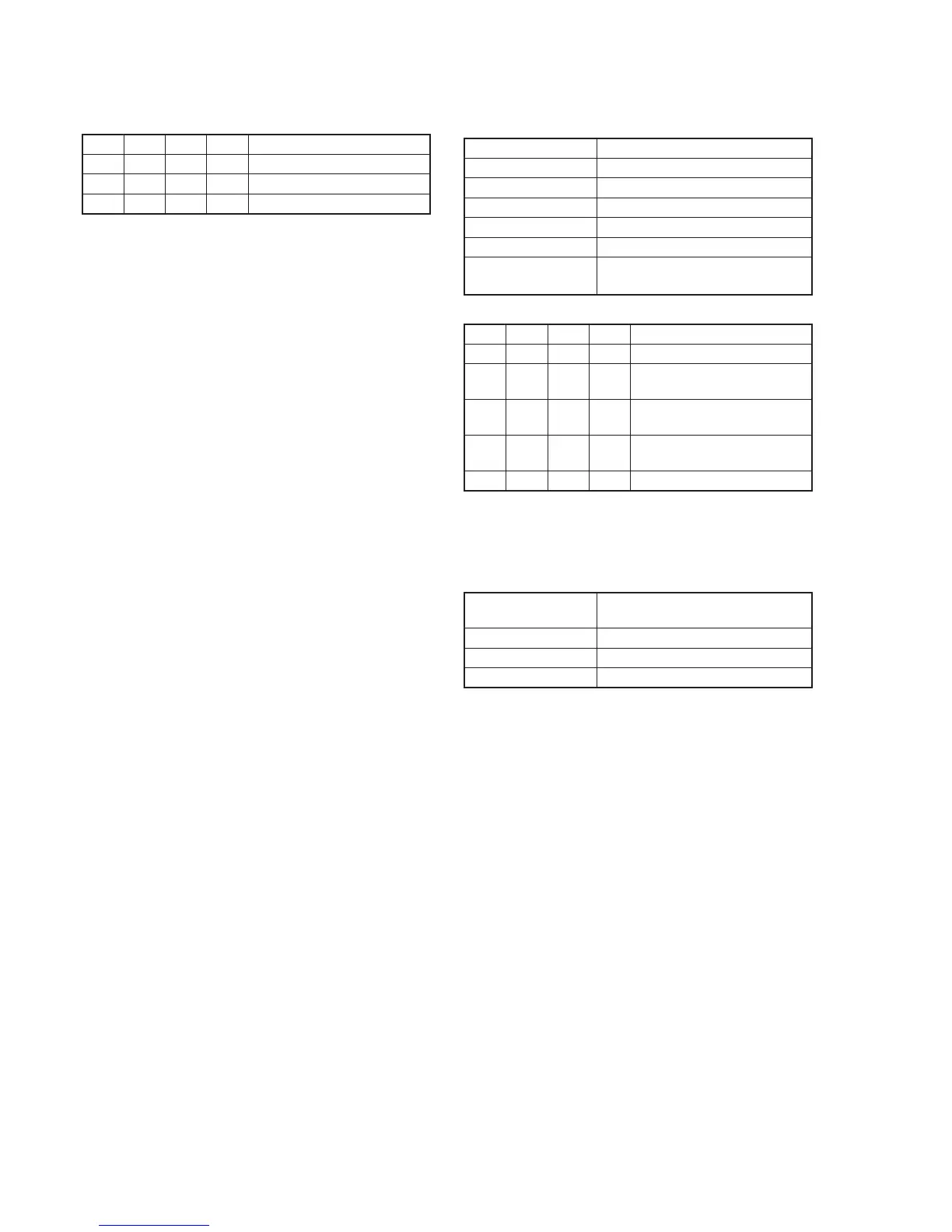
Order Page
Address
Data Procedure
1 0 01 01 Set the data.
2 3 01 30 Set the data, and press PAUSE
button.
3 3 02 Check that the data changes to
“00” with in 5 sec. (Note1)
4 3 03 Check that the data is “00”.
(Note2)
5 0 01 00 Set the data.
Note1: If it isn’t satisfied, there are errors.
Note2: If the data of page: 3, address: 03 is other than “00”, there are
errors. For the error contents, see the following table. (For the bit
values, refer to “5-4. SERVICE MODE”, “4-3. 3. Bit value
discrimination”.)
Bit value of page: 3, Error contents
address: 03 data
bit 2 = 1 or bit 3 = 1 PLL fo fine adjustment is defective
bit 4 = 1 or bit 5 = 1 PLL fo adjustment is defective
bit 6 = 1 LPF fo is defective
4-4. Processing after Completing Adjustments
Order Page
Address
Data Procedure
1 2 30 00 Set the data.
2 3 33 00 Set the data.
3 0 01 00 Set the data.
RadarWRadarWRadarWRadarWRadarW