5-32
4. PSIG GLAY Adjustment (PD-148 board)
Set the PSIG signal level to an appropriate level.
Mode VTR stop
Signal No signal
Measurement Point Pin 6 of CN2105 (PSIG)
Measuring Instrument Oscilloscope
Adjustment Page D
Adjustment Address A7
Specified Value A = 5.00 ± 0.05V
Adjusting method:
Order Page
Address
Data Procedure
1 0 01 01 Set the data.
2 D A7 Change the data and set the PSIG
signal level (A) to the specified
value.
(The data should be “00” to “7F”.)
3 D A7 Press PAUSE button.
4 0 01 00 Set the data.
5. Contrast Adjustment (PD-148 board)
Set the level of the VIDEO signal for driving the LCD to the specified
value. If deviated, the screen image will be blackish or saturated
(whitish).
Mode VTR stop
Signal No signal
Measurement Point Pin 1 of CN2105 (VG)
Measuring Instrument Oscilloscope
Adjustment Page D
Adjustment Address AA
Specified Value A = 3.00 ± 0.05V
Adjusting method:
Order Page
Address
Data Procedure
1 0 01 01 Set the data.
2 D AA Change the data and set the
voltage (A) between the 3 steps
peak and pedestal to the specified
value.
(The data should be “00” to “7F”.)
3 D AA Press PAUSE button.
4 0 01 00 Set the data.
5 Check that the specified value of
“Bright Adjustment” is satisfied.
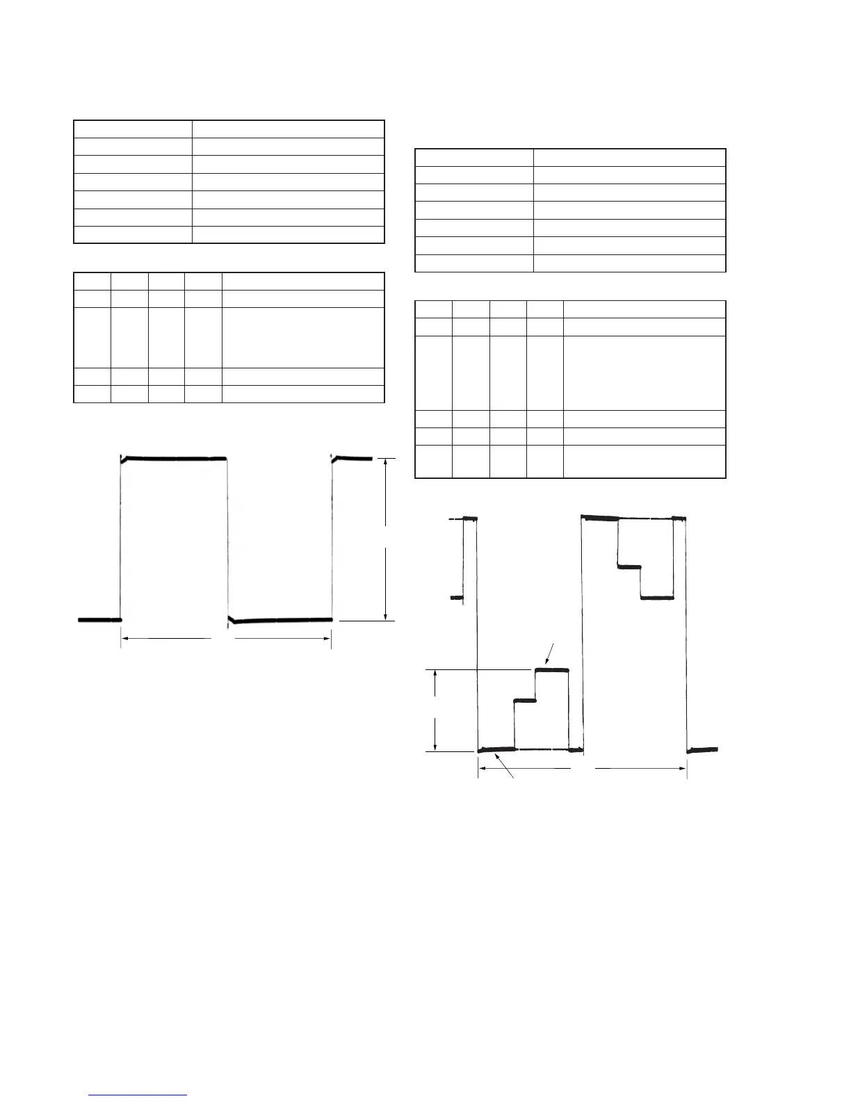
Fig. 5-1-20.
Fig. 5-1-21.
3 steps peak
Pedestal
A
2H
A
2H