5-43
3-3. SERVO AND RF SYSTEM ADJUSTMENT
Before perform the servo and RF system adjustments, check that
the specified value of “36MHz Origin Oscillation Adjustment” of
“CAMERA SYSTEM ADJUSTMENT” is satisfied.
Adjusting Procedure:
1. Cap FG duty adjustment
2. PLL f
0 & LPF f0 adjustment
3. Switching position adjustment`
4. AGC center level
5. APC & AEQ adjustment
6. PLL f0 & LPF f0 fine adjustment
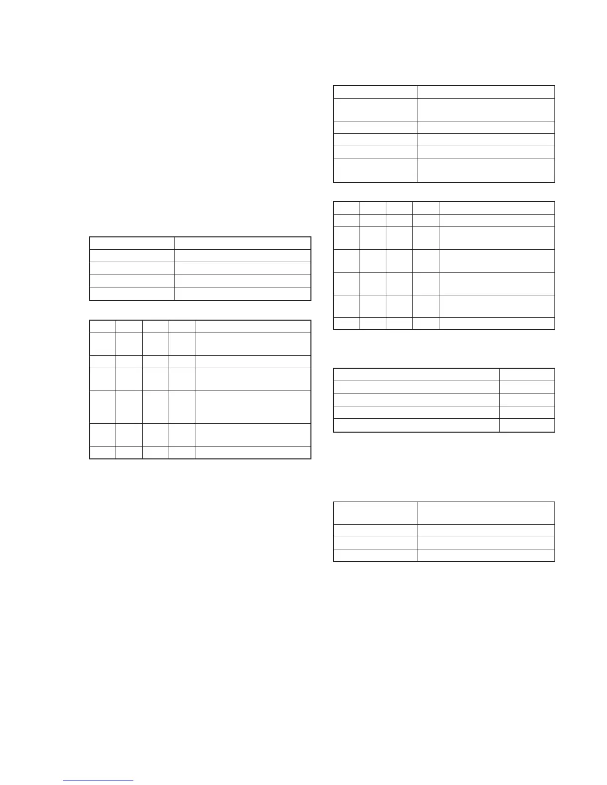
1. Cap FG Duty Adjustment (VC-265 board)
Set the Cap FG signal duty cycle to 50% to establish an appropriate
capstan servo. If deviated, the uneven rotation of capstan and noise
can occur.
Measurement Point Display data of page: 3, address: 03
Measuring Instrument Adjustment remote commander
Adjustment Page C
Adjustment Address 16
Specified Value 00
Adjusting method:
Order Page
Address
Data Procedure
1 Close the cassette compartment
without inserting a cassette.
2 0 01 01 Set the data.
3 3 01 1B Set the data, and press PAUSE
button.
4 3 02 Check that the data changes in
the following order.
“1B” → “2B” → “00”
5 3 03 Check that the data is “00”.
(Note)
6 0 01 00 Set the data.
Note: If the data is “01”, adjustment has errors or the mechanism deck is
defective.
2. PLL fo & LPF fo Adjustment (VC-265 board)
Mode VTR stop
Measurement Point Display data of page: 3, address: 02,
03
Measuring Instrument Adjustment remote commander
Adjustment Page C
Adjustment Address 1F, 20, 22, 29
Specified Value Data of page: 3, address: 02 is “00”.
Data of page: 3, address: 03 is “00”.
Adjusting method:
Order Page
Address
Data Procedure
1 0 01 01 Set the data.
2 3 01 00 Set the data, and press PAUSE
button.
3 3 01 30 Set the data, and press PAUSE
button.
4 3 02 Check that the data changes to
“00” with in 5 sec. (Note)
5 3 03 Check that the data is “00”.
(Note)
6 0 01 00 Set the data.
Note: If it isn’t satisfied, select page: C, address: 21, set the following
data, and press the PAUSE button, and repeat steps 2 to 5.
Setting data
When the data of page: C, address: 21 is “CA”. CE
When the data of page: C, address: 21 is “CE”. C6
When the data of page: C, address: 21 is “C6”. D2
When the data of page: C, address: 21 is “D2” C2
There are errors when it isn’t satisfied even if the above treatment is
done.
If bit2, bit3, bit4, bit5 or bit 6 of the data of page: 3, address: 03 is
“1”, there are errors. For the error contents, see the following table.
(For the bit values, refer to “5-4. SERVICE MODE”, “4-3. 3. Bit
value discrimination”.)
Bit value of page: 3, Error contents
address: 03 data
bit 2 = 1 or bit 3 = 1 PLL fo fine adjustment is defective
bit 4 = 1 or bit 5 = 1 PLL fo adjustment is defective
bit 6 = 1 LPF fo is defective
RadarWRadarWRadarWRadarWRadarW
RadarWRadarWRadarWRadarWRadarW