— 8 —
SELF-DIAGNOSIS FUNCTION
1. SELF-DIAGNOSIS FUNCTION
When problems occur while the unit is operating, the self-diagnosis
function starts working, and displays on the viewfinder or LCD
screen what to do. This function consists of two display; self-
diagnosis display and service mode display.
Details of the self-diagnosis functions are provided in the Instruction
manual.
Note: The “self-diagnosis display” data will be backed up by the coin-type lithium battery of control switch block (FK-1770) BT601. When CN013 of
VC-265 board is disconnected, the “self-diagnosis display” data will be lost by initialization.
2. SELF-DIAGNOSIS DISPLAY
When problems occur while the unit is operating, the counter of the
viewfinder or LCD screen consists of an alphabet and 4-digit
numbers, which blinks at 3.2 Hz. This 5-character display indicates
the “repaired by:”, “block” in which the problem occurred, and
“detailed code” of the problem.
3. SERVICE MODE DISPLAY
The service mode display shows the last self-diagnosis codes shown in the past.
3-1. Display Method
While pressing the “BACK LIGHT” key, set the switch from OFF to “VCR or PLAYER”, and continue pressing the “BACK LIGHT” key for
5 seconds continuously. The service mode will be displayed, and the counter will show the backup No. and the 5-character self-diagnosis
codes.
3-2. Backup No.
The backup No. in the [] indicates the order in which the problem occurred. (If the number of problems which occurred is less than 6, only the
number of problems which occurred will be shown.)
[1] : Occurred first time [4] : Occurred fourth time
[2] : Occurred second time [5] : Occurred fifth time
[3] : Occurred third time [6] : Occurred the last time
Note: Switching of the backup No. can’t be done.
3-3. End of Display
Turning OFF the power supply will end the service mode display.
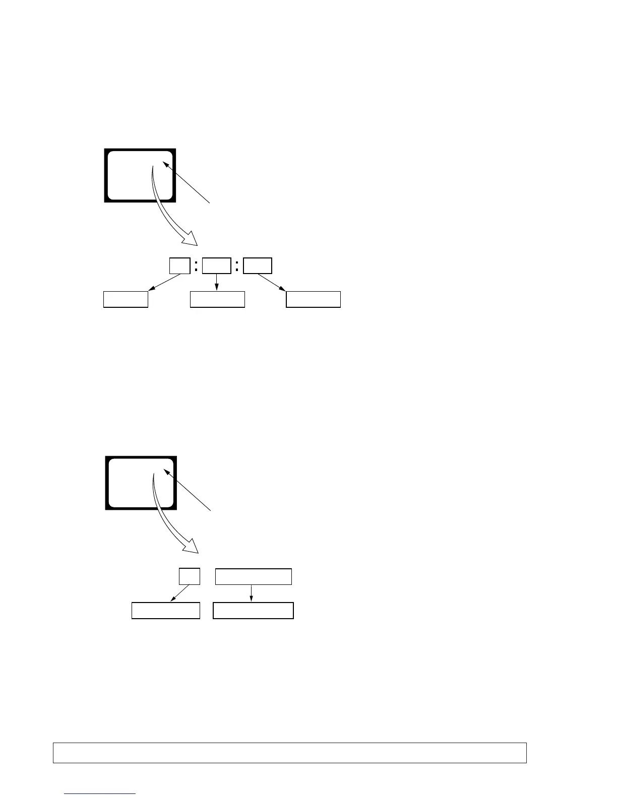
Order of previous errors
Backup No.
Self-diagnosis Codes
C : 3 1 : 1 1
[3]
Lights up
Viewfinder or LCD screen
[3] C : 3 1 : 1 1
1 1
3 1C
Repaired by:
Refer to page 9.
Self-diagnosis Code Table.
Indicates the appropriate
step to be taken.
E.g.
31 ....Reload the tape.
32 ....Turn on power again.
Block
Detailed Code
Blinks at 3.2Hz
C : Corrected by customer
H : Corrected by dealer
E : Corrected by service
engineer
Viewfinder or LCD screen
C : 3 1 : 1 1