166 Sun Fire V890 Server Owner’s Guide • September 2004
Reference for the Serial Port A and B
Connectors
The serial port conforms to EIA-423 and EIA-232D specifications.
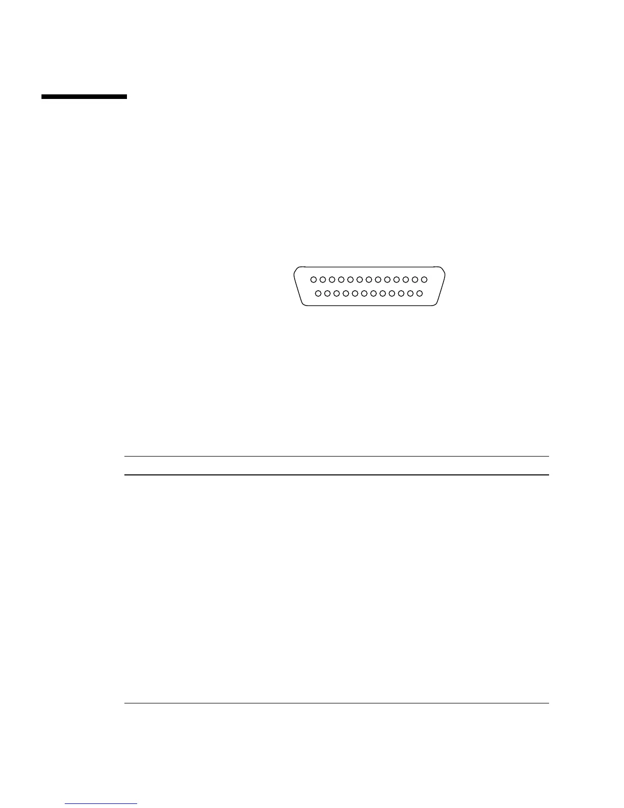
Serial Port Connector Diagram
Serial Port Signals
Signal descriptions ending in “A” indicate that the signal is associated with the port
provided by a standard DB-25 serial cable or the connector labeled “A” on the
optional DB-25 splitter cable. Signal descriptions ending in “B” indicate that the
signal is associated with the port provided by the connector labeled “B” on the
optional DB-25 splitter cable.
Pin Signal Description Pin Signal Description
1 No Connection 14 Transmit Data B
2 Transmit Data A 15 Transmit Clock A (External)
3 Receive Data A 16 Receive Data B
4 Ready To Send A 17 Receive Clock A
5 Clear To Send A 18 Receive Clock B
6 Synchronous A 19 Ready To Send B
7 Signal Ground A 20 Data Terminal Ready A
8 Data Carrier Detect A 21 No Connection
9 No Connection 22 No Connection
10 No Connection 23 No Connection
11 Data Terminal Ready B 24 Transmit Clock A (Internal)
12 Data Carrier Detect B 25 Transmit Clock B
113
25 14