Chapter 3 Hardware Configuration 49
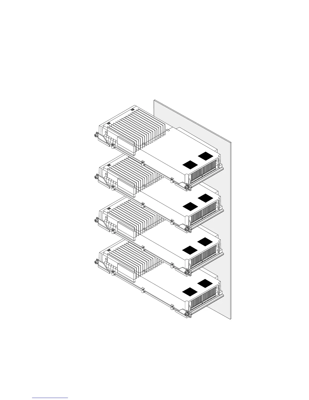
The following illustration shows the four CPU/Memory board slots on the system
motherboard. The slots are labeled A through D from bottom to top. The virtual
processors (CPUs) in the system have unique numbers, depending on the slot where
each CPU/Memory board resides. For example, a CPU/Memory board installed in
slot D always contains CPUs 5 and 21 and 7 and 23, even if there are no other
CPU/Memory boards installed in the system.
5,21
7,23
Slot D
Slot C
Slot B
Slot A
4,20
6,22
1,17
3,19
0,16
2,18