6-34 POWER UNIT
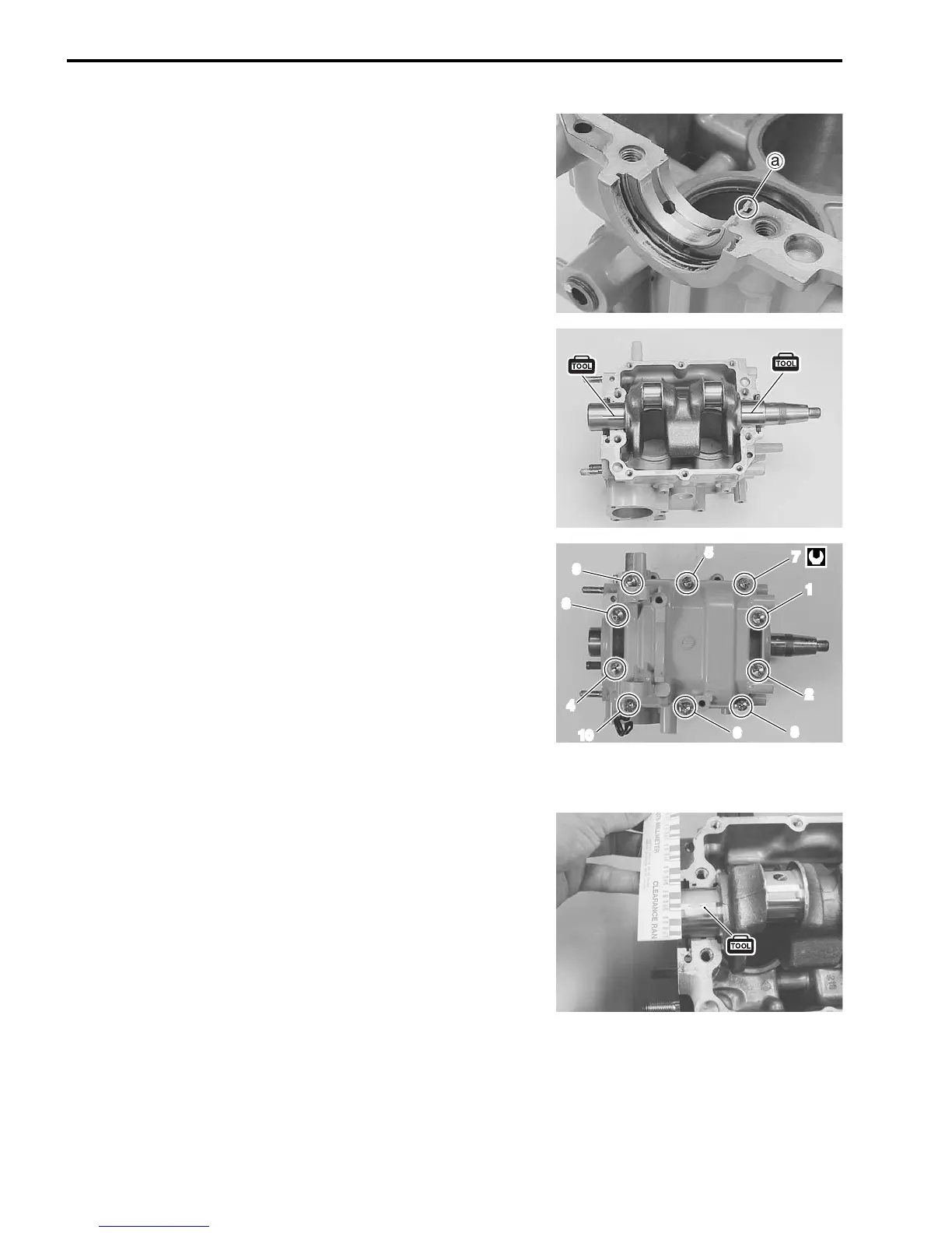
2. Install crankshaft main bearing to cylinder and crankcase.
NOTE:
• Reassemble each bearing to its original position.
• Align the tab a of bearing with notch in cylinder and crank-
case.
• Do not apply oil to bearing.
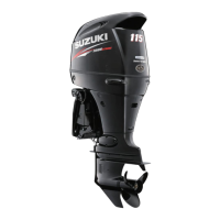
3. Install crankshaft to cylinder.
4. Place a piece of Plastigauge across full width of bearing
(parallel to crankshaft) on journal.
Do not place Plastigauge over oil hole.
09900-22301: Plastigauge
5. Install crankcase (with the bearing) to cylinder.
6. Apply engine oil to crankcase bolts and tighten bolts to the
specified torque following the order indicated.
Crankcase bolt:
6 mm 14 N·m (1.4 kg-m, 10.0 lb-ft)
8 mm 25 N·m (2.5 kg-m, 18.0 lb-ft)
NOTE:
• The crankcase must be torqued to specification in order to
assure proper compression of Plastigauge and accurate read-
ing of clearance.
• Do not rotate crankshaft while Plastigauge is installed.
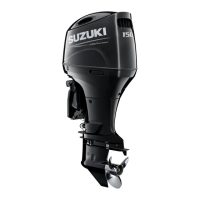
7. Remove crankcase from the cylinder.
8. Measure the compressed plastigauge width at its widest
point.
NOTE:
For bearing replacement, see the “SELECTION OF MAIN
BEARING” section on page 6-35.
7
1
2
8
6
4
10
3
9
5