12-26 DF9.9T/TH “K8” (’08) MODEL
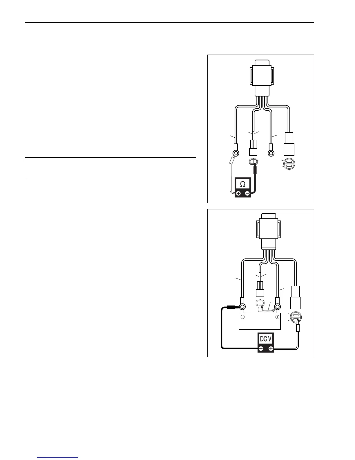
PT MOTOR RELAY
INSPECTION
1. Disconnect battery cable from battery.
2. Disconnect all cables/lead wires from PT relay.
3. Check resistance between each two (2) lead wires.
09930-99320: Digital tester
Tester range: Ω (Resistance)
Between “P” wire and “B” wire: 25 – 37 Ω
Between “Lbl” wire and “B” wire: 25 – 37 Ω
4. Connect “R” wire to positive + terminal, and black wire to
negative - terminal of 12 V battery.
5. Temporarily connect a jumper wire from the “P” lead wire to
the battery positive + terminal, then check voltage between
“G” wire and “B” wire.
09930-99320: Digital tester
Tester range: DCV
Between “G” wire and “B” wire: 12 V (Battery voltage)
6. Temporarily connect a jumper wire from the “Lbl” lead wire to
the battery positive + terminal, then check voltage between
“Bl” wire and “B” wire.
Between “Bl” wire and “B” wire: 12 V (Battery voltage)
7. If inspection in step 3 and/or step 5, 6 fails, replace PT relay.
Each operation test must be performed within 3 – 5
seconds to avoid overheat damage to the relay coil.
P
Lbl
R
B
Bl
G
R
1
Bl
G
BATTERY
12 V
P
Lbl
B
1. Jumper wire



 To Next Page