FUEL SYSTEM 4-3
FUEL LEAKAGE CHECK PROCEDURE
After performing any fuel system service, always be sure there
is not fuel leakage by checking as follows.
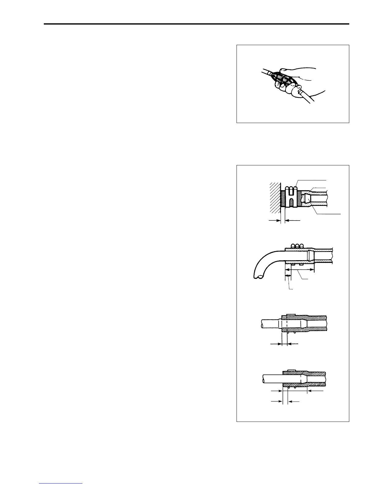
1. Squeeze fuel primer bulb until you feel resistance.
2. Once pressurized, check all connections and components
for any signs of leakage.
FUEL HOSE CONNECTION
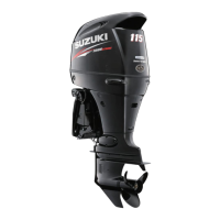
Note that fuel hose connection varies with each type of pipe.
Be sure to connect and clamp each hose correctly by referring to
the figure.
• For type “A” (short barbed end) pipe, hose must completely
cover pipe.
• For type “B” (bent end) pipe, hose must cover straight part of
pipe by 20 – 30mm (0.8 – 1.2 in.).
• For type “C” pipe, hose must fit up against flanged part of
pipe.
• For type “D” pipe, hose must cover pipe by 20 – 30 mm (0.8 –
1.2 in.).
Clamp (Clip)
Hose
Joint pipe
3 – 7 mm
(0.1 – 0.3 in)
“A”
“B”
“C”
“D”
20 – 30 mm
(0.8 – 1.2 in.)
3 – 7 mm
(0.1 – 0.3 in.)
3 – 7 mm (0.1 – 0.3 in.)
20 – 30 mm
(0.8 – 1.2 in.)
3 – 7 mm
(0.1 – 0.3 in.)