IGNITION AND ELECTRICAL 3-23
ELECTRIC STARTER SYSTEM
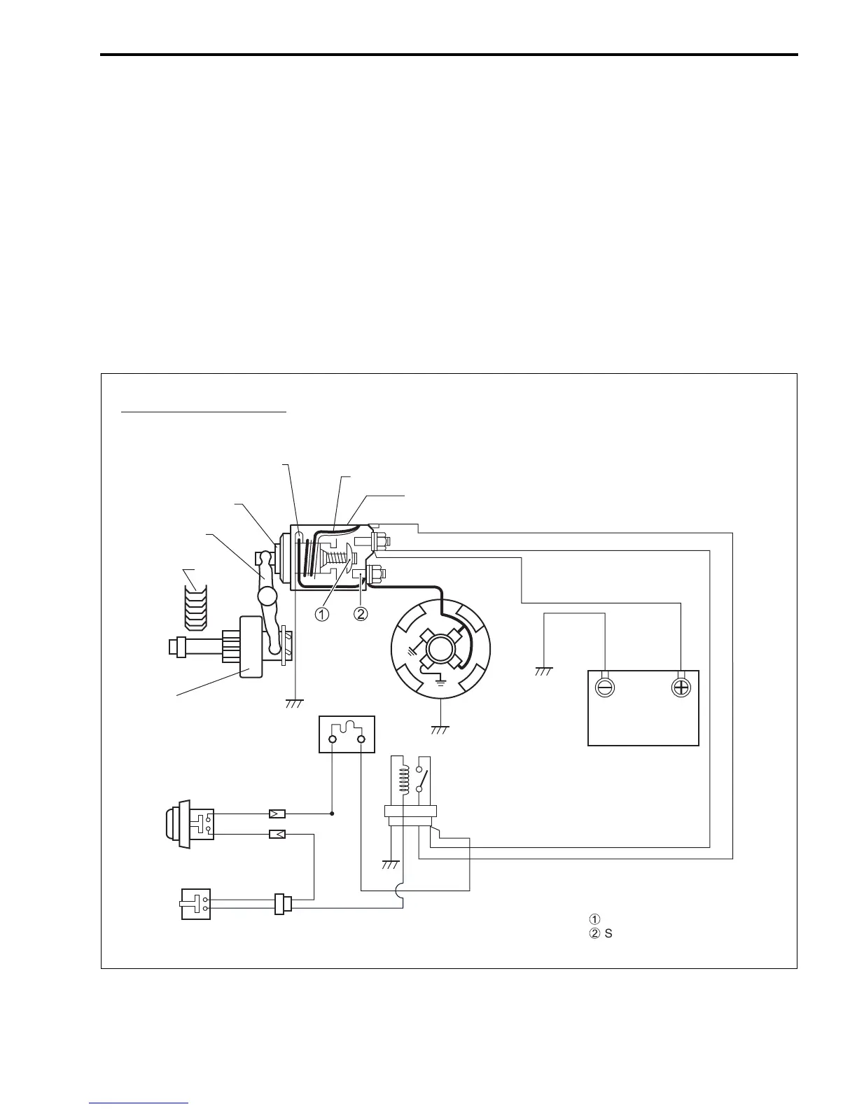
OUTLINE
The starting circuit consists of the battery, starting motor, ignition switch (or starter button), neutral switch
and related electrical wiring.
These components are connected electrically as shown in figure below.
STARTING SYSTEM CIRCUIT
In the circuit shown in figure below, the magnetic switch coils are magnetized when the starter button is
closed (Starter button depressed).
The resulting plunger and pinion shift lever movement causes the pinion to engage the engine flywheel
gear, the magnetic switch main contacts to close, and engine cranking to take place.
When the engine starts, the pinion over-running clutch protects the armature from excessive speed until the
starter button is opened, at which time the torsion spring causes the pinion to disengage.
Pinion &
over-running clutch
Ring gear
Shift lever
Plunger
Hold-in coil
Pull-in coil
Magnetic switch
Starter
motor
Battery
Fuse 20A
W/R
B
Br
Br
W
R
R
R
R
R
R
W/RW/RW/R
B
Br
Br
W
RR
R
R
R
R
R
R
Y/GY/G
Y/G Y/GY/G Y/G
Starter button
Neutral switch
Starter relay
Movable contact
Stationary contact
For Tiller handle model