10-10 DF9.9/15 “K6” (’06) MODEL
PEAK VOLTAGE
Requirements for peak voltage measurement
• Remove all spark plugs to eliminate the variables at cranking speed.
• Crank with recoil starter.
• Use a STEVENS peak voltage tester, Model CD-77.
• Use the 6-pin connector test cord (Part No. 09930-89920).
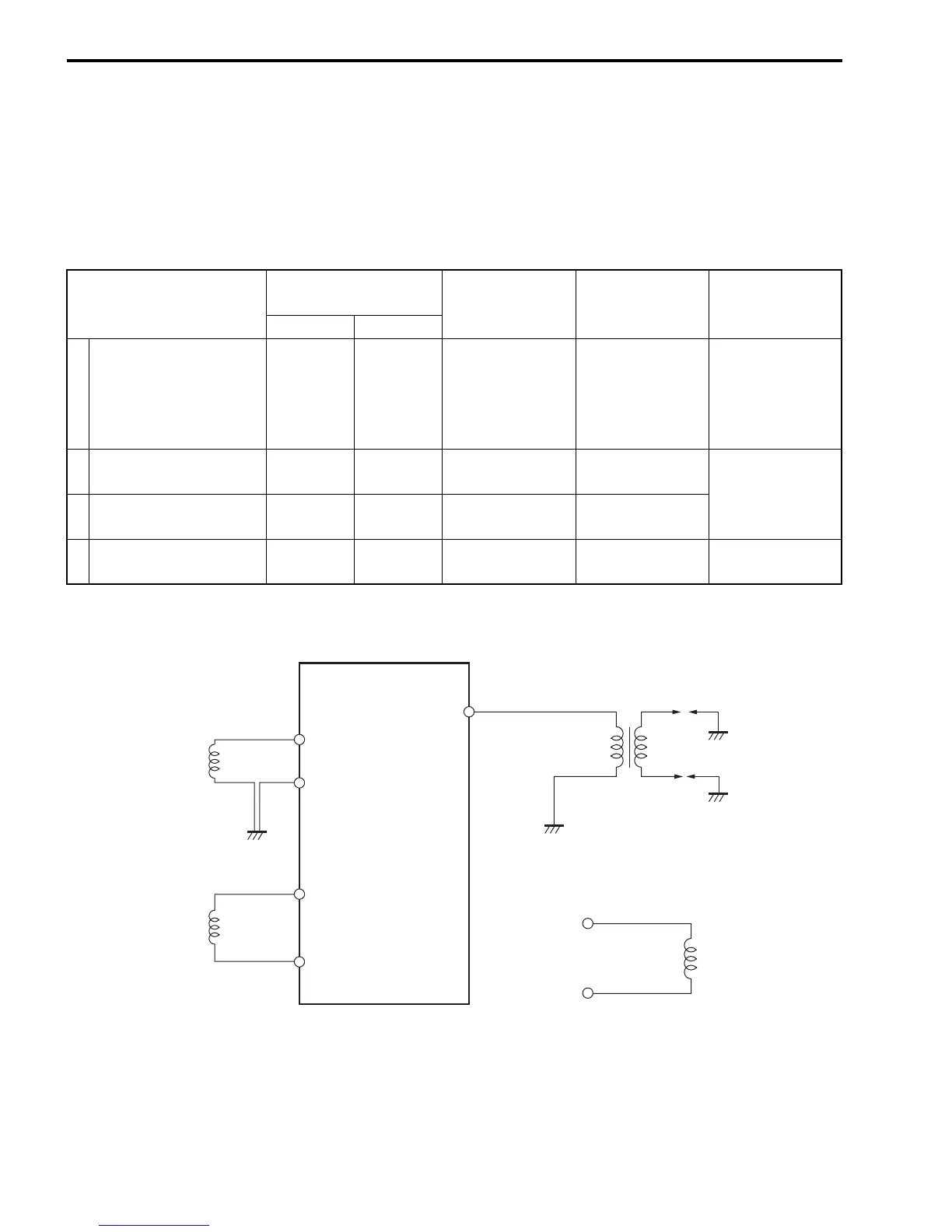
Testing sequence
Tester probe
connection
Peak voltage Tester range Remarks
+ (Red) - (Black)
1 CDI output Orange Black 128 V or over NEG 500
• With ignition
coil connected
• Use the 6-pin
connector test
cord.
2
Condenser charge coil
output
Green Black/Red 15 V or over POS 50
With CDI unit
disconnected
3
Pulser coil output
Red/Black
Black
(Ground)
0.8 V or over SEN 5
4
Battery charge coil out-
put
Red Yellow 5.6 V or over POS 50
With rectifier
disconnected
Test 1
Ignition coil
Battery charge coil
Pulser coil
Test 4
CDI unit
Test 3
Condenser
charge coil
Test 2
B
R
Y
R
Y
R/B
B
B
R/B
B
G
B/R
G
B/R
OO