3-38 IGNITION AND ELECTRICAL
ASSEMBLY
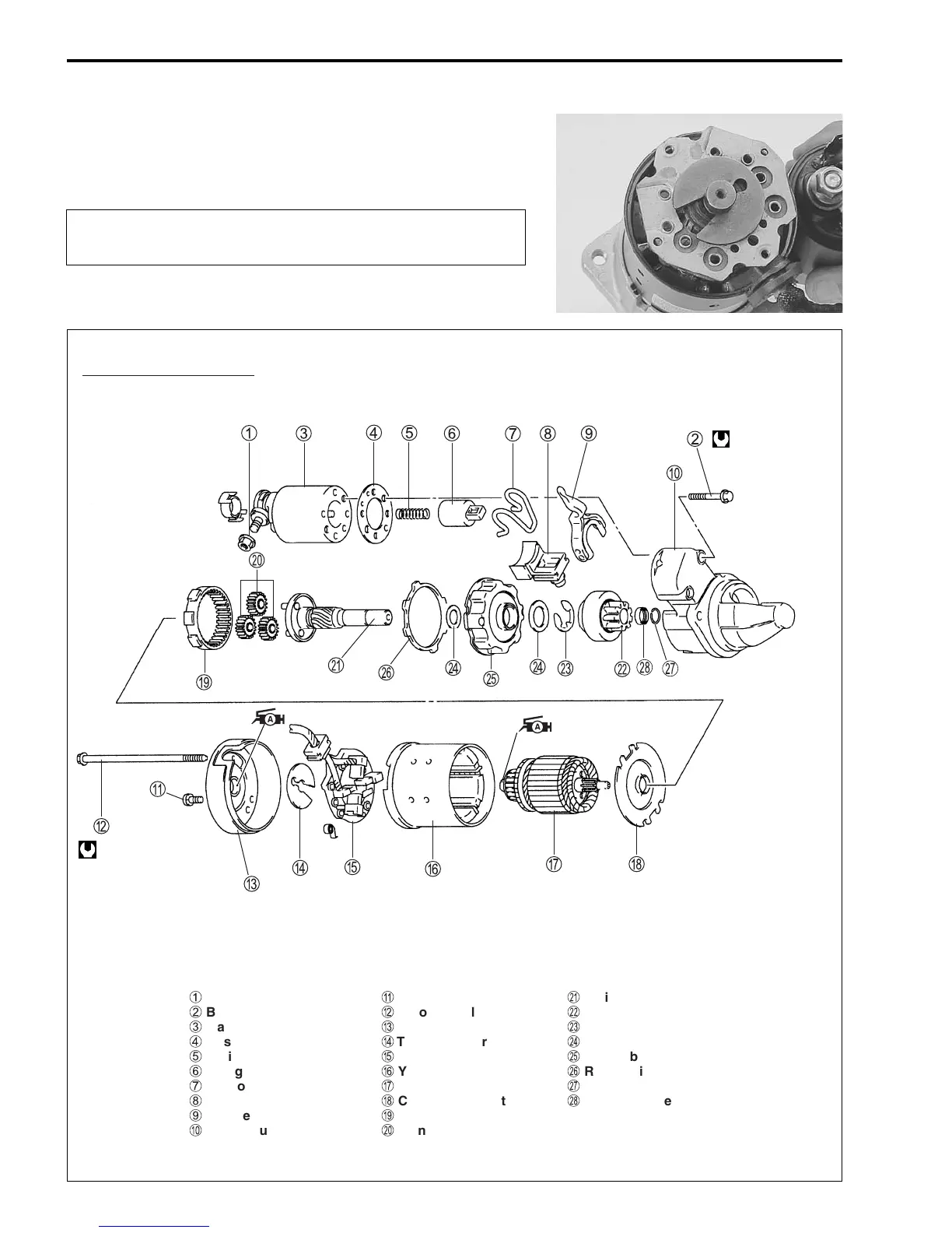
Assembly is reverse order of disassembly with special attention
to the following steps.
When installing pinion shift lever, refer to figure in construction
diagram for installation direction.
When installing armature, use care to avoid breaking
brushes.
7 N
.
m
(0.7 kg-m,
5.1 lb-ft)
5.5 N
.
m
(0.55 kg-m, 4.0 lb-ft)
1
Nut
2
Bolt
3
Magnetic switch
4
Gasket
5
Spring
6
Plunger
7
Torsion spring
8
Rubber packing
9
Shift lever
0
Front housing
A
Screw
B
Through bolt
C
Rear cover
D
Thrust washer
E
Brush holder
F
Yoke
G
Armature
H
Center cover plate
I
Internal gear
J
Planetary gear
K
Pinion shaft
L
Pinion
M
E-ring
N
Washer
O
Center bracket
P
Rubber ring
Q
Stopper ring
R
Pinion stopper
Construction diagram