6 – Modules
3 LOCK/UNLOCK button
o This button locks/unlocks routing setting change
operations for the unit. This is always locked at the time of
start up.
o When set to “LOCK”, tapping INPUT SOURCE (1) and OSC
(3) buttons will not change settings. Furthermore, the
8ch BLOCK, 16ch BLOCK, 24ch BLOCK and BATCH SETUP
buttons will also be disabled. However, tapping the Others
button and switching to the INPUT SOURCE SELECT
Screen is possible.
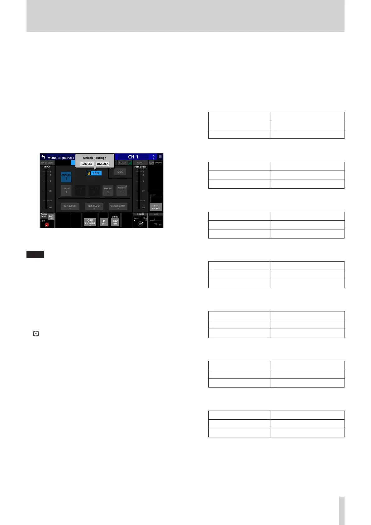
o When set to “LOCK”, tap this button to open a confirmation
message. Tap the UNLOCK button to close the message
and set it to “UNLOCK”. Tapping the CANCEL button on
the confirmation message will close it and maintain the
locked state.
o Tap this button when set to “UNLOCK” to switch it to
“LOCK”.
NOTE
The LOCK/UNLOCK button (1) setting is shared by the
following routing setting screens.
i MODULE (INPUT) Screen
i MODULE (OUTPUT) Screen
i INPUT SOURCE SELECT Screen
i OUTPUT PORT SELECT Screen
i DIRECT OUT PORT SELECT Screen
i INSERT SEND PORT SELECT Screen
i INSERT RETURN PORT SELECT Screen
4 icon
Tap this icon to open the TALKBACK/OSCILLATOR page of the
MONITOR SETUP Screen. (See “Making talkback and built-in
oscillator settings” on page 57.)
5 OSC button
When the LOCK/UNLOCK button (3) is set to “UNLOCK”, tap
this button to turn internal oscillator input on or off (default).
When on, the signal from the internal oscillator will be input
to the selected module while maintaining the input source
setting for that module. (Default: OFF)
When on, this button will appear highlighted and the INPUT
SOURCE selection (2) button area will be dimmed.
6 POST D. TRIM level meter(s)
This shows the signal level(s) after the D. TRIM.
7 Analog GAIN knob and indicator
o When the input source of the selected module is
“ANALOG” or “SB-16D connected by built-in Dante”, this
will show an analog gain knob that can be used to adjust
the input level of the MIC/LINE input jacks on this unit or
the SB-16D.
Turn LCD knob 1 (lit red) to adjust it.
When Analog Reference Level is +6 dBu and Digital
Reference Level is -9 dBFS
PAD button setting Range
OFF +3 (default) – +57
ON -17 – +37
When Analog Reference Level is +4 dBu and Digital
Reference Level is -20 dBFS
PAD button setting Range
OFF +12 (default) – +66
ON -8 – +46
When Analog Reference Level is +4 dBu and Digital
Reference Level is -18 dBFS
PAD button setting Range
OFF +10 (default) – +64
ON -10 – +44
When Analog Reference Level is +4 dBu and Digital
Reference Level is -16 dBFS
PAD button setting Range
OFF +8 (default) – +62
ON -12 – +42
When Analog Reference Level is +4 dBu and Digital
Reference Level is -14 dBFS
PAD button setting Range
OFF +6 (default) – +60
ON -14 – +40
When Analog Reference Level is 0 dBu and Digital
Reference Level is -20 dBFS
PAD button setting Range
OFF +8 (default) – +62
ON -12 – +42
When Analog Reference Level is 0 dBu and Digital
Reference Level is -18 dBFS
PAD button setting Range
OFF +6 (default) – +60
ON -14 – +40
o The indicators to the left of the Analog GAIN knobs appear
to light as shown below depending on the input level.
Red: -3 dBFS, Green: -40 dBFS
o When the input source of the selected module is an
“ANALOG” stereo module, 2 Analog GAIN knobs will be
shown.
Use LCD knobs 1–2 (lit red) to adjust them.
TASCAM Sonicview 16/Sonicview 24 V1.1.0 125

 Loading...