2 – Names and Functions of Parts
GPIO connector overview
The GPIO connector on the back of the unit is a parallel control connector that allows this unit to control and be controlled by other
devices.
GPIO connector function settings can be changed on the USER DEFINED CONTROLS Screen GPIO-IN and GPIO-OUT pages. (See “USER
DEFINED CONTROLS screen” on page 42.)
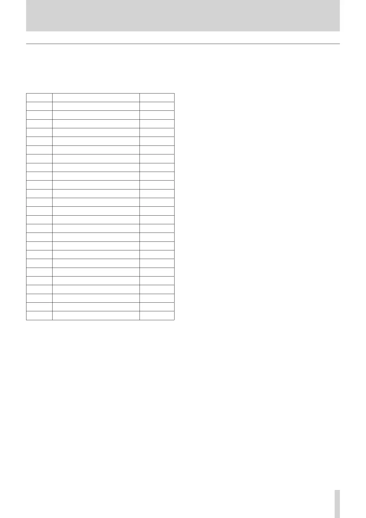
The pin assignments are as follows.
Pin No. Function IN/OUT
1 GND -
2 GPIO IN 2 IN
3 GPIO IN 4 IN
4 GPIO IN 6 IN
5 GPIO IN 8 IN
6 NC -
7 NC -
8 NC -
9 GPIO OUT 2 OUT
10 GPIO OUT 4 OUT
11 GPIO OUT 6 OUT
12 GPIO OUT 8 OUT
13 NC -
14 GPIO IN 1 IN
15 GPIO IN 3 IN
16 GPIO IN 5 IN
17 GPIO IN 7 IN
18 NC -
19 NC -
20 GND -
21 GPIO OUT 1 OUT
22 GPIO OUT 3 OUT
23 GPIO OUT 5 OUT
24 GPIO OUT 7 OUT
25 +5V -
IN: For command input
i Internal circuit with +5V pull-up
i Operates with low signal input of 50 msec or longer
OUT: For command and tally output
i Internal circuit is open collector (10Ω output impedance)
i 20V dielectric strength, 35mA maximum current
+5V: 50mA maximum supplied current
TASCAM Sonicview 16/Sonicview 24 V1.1.0 13