2 – Names and Functions of Parts
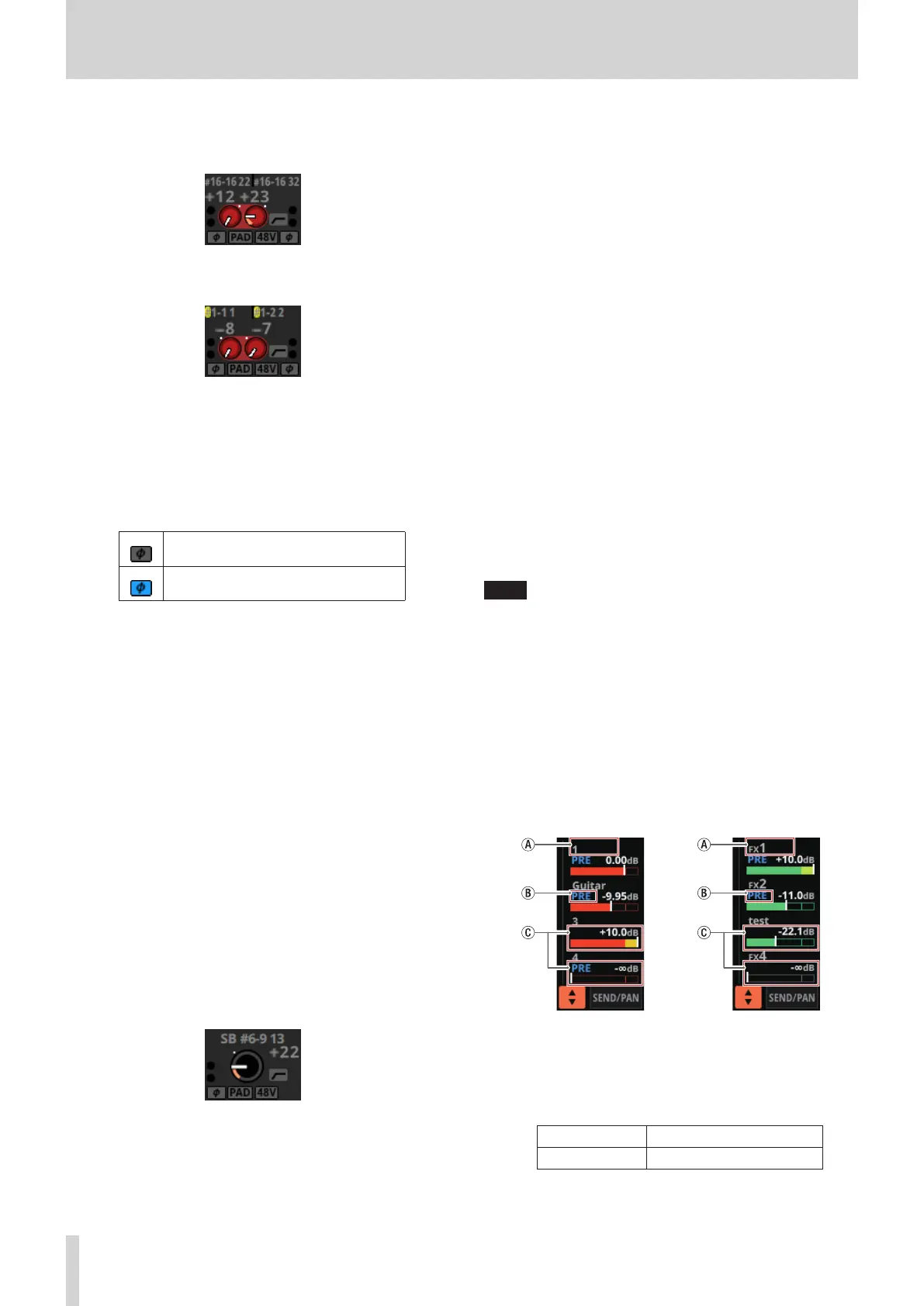
i When a module is stereo, if a Dante port that has a
mounted SB-16D assigned is selected, “#[ID] [port
number]” will be shown.
If it is a virtually-mounted SB-16D, the # background
will be yellow.
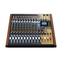
b These indicators appear to light as shown below
depending on the input level. When a module is stereo,
two sets of module indicators will be shown separately
left and right.
Red: -3 dBFS, Green: -40 dBFS
c This shows the input signal phase setting status. When
a module is stereo, two module phase settings will be
shown separately left and right.
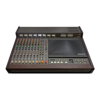
Normal
Reversed
d
This shows the
-
20dB pad setting status when the input
source of the selected module is
“ANALOG” or
“SB-16D
connected by built-in Dante”
.
When on, the icon will
appear highlighted.
If the input sources for both the left and right channels
of a stereo module are “ANALOG” or “SB-16D connected
by built-in Dante”, this shows the left channel setting.
e This shows the phantom power (+48V) setting status
when the input source of the selected module is
“ANALOG” or “SB-16D connected by built-in Dante”.
When on, the icon will appear highlighted.
If the input sources for both the left and right channels
of a stereo module are “ANALOG” or “SB-16D connected
by built-in Dante”, this shows the left channel setting.
f This shows the HPF setting status. When on, the icon
will appear highlighted.
g When the input source of the selected module is
“ANALOG” or “SB-16D connected by built-in Dante”,
this will show an analog gain knob and the input level
of the unit or SB-16D MIC/LINE input jacks. When a
module is stereo, two knobs and input level values will
be shown for the module.
A black knob that cannot be operated will be shown
if the input source is an SB-16D for which control
privileges are not held.
h A D.TRIM knob and the digital trim value will be shown
when the input source of the selected module is not
“ANALOG” or “SB-16D connected by built-in Dante”.
o Tap this area to show the selection frame. When the
selection frame is shown, corresponding LCD knobs can
be used to adjust the parameters shown.
o When the selection frame is shown, tap this area to open
the MODULE (INPUT) Screen for the selected module. (See
“MODULE (INPUT) Screen” on page 124.)
2 GATE/EXPANDER/DE-ESSER area
o This shows the response graphs and gain reduction
meters of dynamics effects.
o Tap this area to open the MODULE (GATE/EXPANDER/
DE-ESSER) Screen for the selected module. (See “MODULE
(GATE/EXPANDER/DE-ESSER) screens” on page 132.)
3 HPF/EQ area
o This shows graphs of the HPF and EQ frequency
responses.
o Tap this area to open the MODULE (EQ) Screen for the
selected module. (See “MODULE (EQ) Screen” on page
134.)
4 COMP/DUCKER area
o This shows the response graphs and gain reduction
meters of dynamics effects.
o Tap this area to open the MODULE (COMP/DUCKER) Screen
for the selected module. (See “MODULE (COMP/DUCKER)
Screen” on page 138.)
5 Level meters
This shows the level of the signal at the set metering point.
(See “METERING POINT page” on page 38.) (See “MODULE
(OVERVIEW) Screen” on page 112.)
NOTE
i If the selected module is stereo, a stereo level meter will be
shown.
i Each level meter has an overload indicator at its top. They will
appear to light red when the signal level reaches or exceeds
-0.00026 dBFS (16-bit full-scale value).
i When a level overload occurs, the entire bar meter will light
red.
i The area below -60 dBFS at the bottom of the level meters
will light when above -70 dBFS.
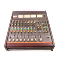
6 SEND area
o This shows the states of SEND settings to MIX 1–22 and FX
1–4 buses 4 at a time.
a This shows the user module name for the MIX 1–22 or
FX RTN 1–4 module. If the name has not been defined,
the module name will be shown as “1” or “FX 1”, for
example.
b This shows the PRE/POST setting used for MIX 1–22
and FX 1–4 buses.
No indicator Set to POST
PRE Set to PRE
16 TASCAM Sonicview 16/Sonicview 24 V1.1.0