2 – Names and Functions of Parts
c These show the assignment state and send level to MIX
1–22 and FX 1–4 buses in AUX mode.
MIX 1–22 bus Shown in orange
FX 1–4 bus Shown in green
This will be gray when not assigned.
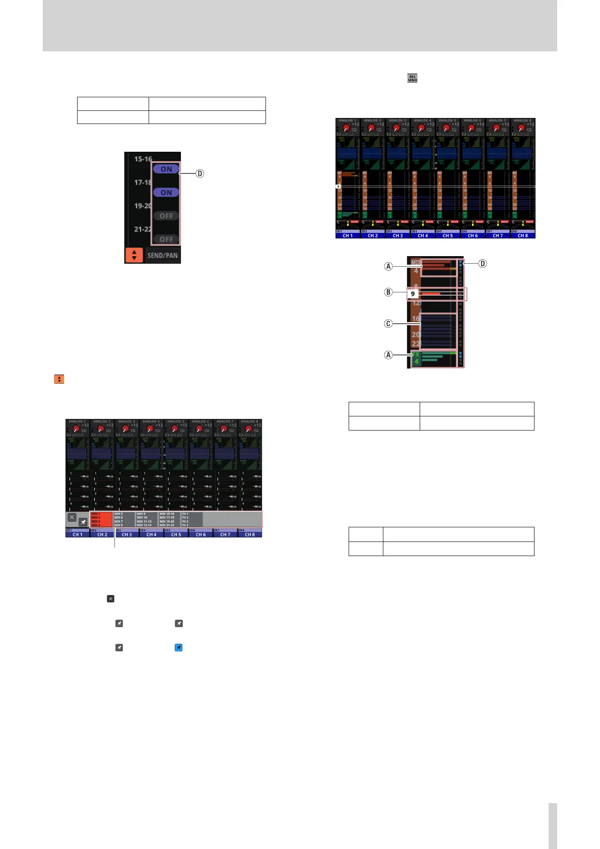
d Purple rounded buttons are shown when GROUP mode
MIX 1–22 buses are ON. These appear but cannot be
turned on/off on the Home Screen.
o Tap a SEND level to show the selection frame. When the
selection frame is shown, corresponding LCD knobs can
be used to adjust the SEND level shown.
o Tap the SEND level while pressing the HOME key to set the
SEND level for that bus to 0 dB. (See “12 – List of shortcut
operations” on page 206.)
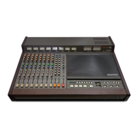
7 button
Tap this button to show the selection window for the bus
shown in the SEND area.
bus selection button
i Tap a bus selection button to open the selected bus
group in the SEND area.
i Tap the button at the top left of the selection
window to close it.
i When the button is off ( ), tapping the bus selection
button will automatically close this window.
i When the button is on ( ), tapping a bus selection
button will not close this window.
8 SEND/PAN button
Tap this button to open the MODULE (SEND/PAN) Screen.
(See “MODULE (SEND/PAN) Screen” on page 140.)
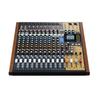
9 ALL SEND button ( )
Tap this button to change the SEND area display to ALL SEND
bus display.
a These show the assignment state and send level to MIX
1–22 and FX 1–4 buses in AUX mode.
MIX 1–22 bus Shown in orange
FX 1–4 bus Shown in green
This will be gray when not assigned.
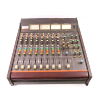
b When the selection frame is shown, corresponding LCD
knobs can be used to adjust the SEND levels shown.
The selection frame can also be swiped up and down
to select MIX 1–22 and FX 1–4 buses.
c These show the assignment state and send level to MIX
1–22 buses in GROUP mode. These appear but cannot
be adjusted.
OFF Shown in dark purple
ON Shown in bright purple
d These appear light blue when the PRE/POST setting
used for MIX 1–22 and FX 1–4 buses is “PRE”.
o Tap the ALL SEND bus area to switch to showing 4 buses
in the tapped area.
0 PAN area
o This shows the pan/balance setting of the signals sent to
the MAIN L/R bus as well as the MAIN L/R bus assignment
status.
o Tap this area to show the selection frame. When the
selection frame is shown, corresponding LCD knobs can
be used to adjust the pan/balance of the sent signals.
o Tap this area while pressing the HOME key to set the
tapped pan/balance setting to center (C). (See “12 – List of
shortcut operations” on page 206.)
o When the selection frame is shown, tap this area to open
the MODULE (SEND/ PAN) Screen. (See “MODULE (SEND/
PAN) Screen” on page 140.)
TASCAM Sonicview 16/Sonicview 24 V1.1.0 17