RUN EXCITE: Service & Maintenance Manual - rev. 1.5
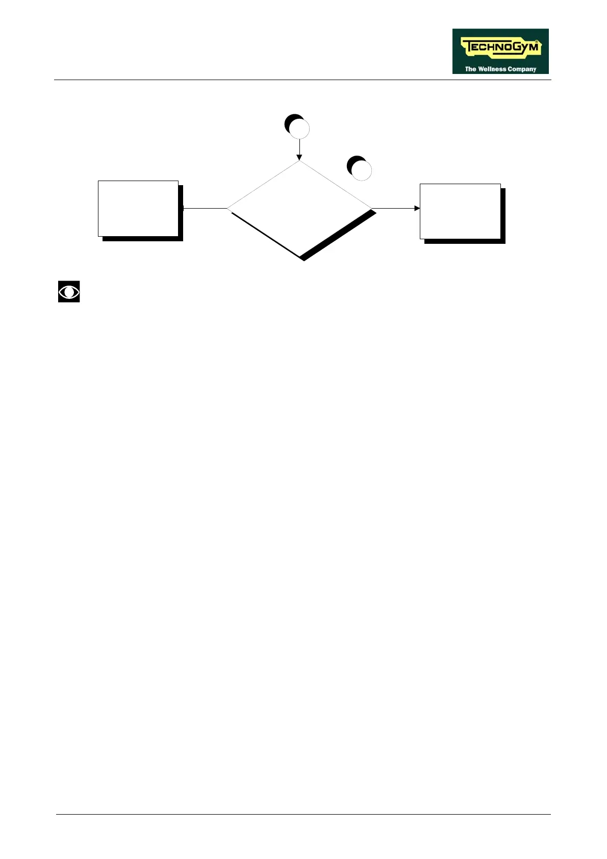
Is the emergency signal at the
output of the digital plan board
correct?
Replace cable TRM-20
YES
NO
10
Replace the digital
B
plan board
It mi
logi
gh helpful to refer to the theoretical explanation of the emergency stop
c, p n .4. “Emergency stop management”
Foll e pr t se the problem. Take particular care with the
che ighlight by c
(1) Place the tester pr
roxima 220
(2) for step ) but relay.
(3) for step ) but lay.
(4) ce the er p be
approximately 11.
(5) As for step (4) but
(6) Place the tester pr oard.
e measu val
(7) or step but 9 and 12 of connector X2 of the download board.
(8) or step but
) As for step (6) but across terminals 9 and 12 of patch connector F.
(10) As for step (6) but across pins 4 and 6 of patch connector CN9 on the digital plan board.
t also be
rovided i
oce re s
paragraph 3
ow th
cks h
du
ed
ep by step to correctly diagno
ircled numbers, which are described in detail below:
obes across pins L1 and L2 of the inverter. The measured voltage should be
VAC. app tely
As (1 across terminals 2 and 6 of the
As (1 across terminals 4 and 8 of the re
Pla test robes across pins 0 and 1 of the relay. The measured value should
7 Vdc.
across the R+ and R- terminals of the elevation + cutout board.
obes across pins 2 and 3 of connector X4 on the elevation + cutout b
ue should be approximately 0 Vdc. Th red
As f (6) across terminals
As f (6) across terminals 9 and 12 of connector X1 of the download board.
(9
Page 6.33
 Loading...


