RUN EXCITE: Service & Maintenance Manual - rev. 1.5
Page 3.12
3.2. TREAD BELT MOTOR DRIVE
3.2.1. MECHANICS
The tread belt is actuated by the motor through a linkage consisting of the motor pulley, the driving
roller and the belt which connects them. In this way, a given belt motor speed corresponds to a
predetermined linear tread belt speed.
3.2.2. CONTROLS
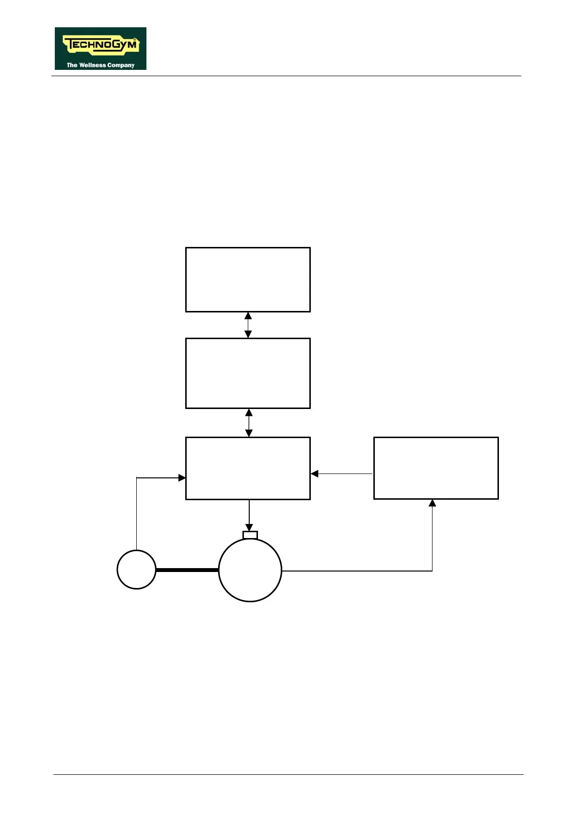
The control block diagram is as follows:
Digital Plan Board
Download Board
Inverter
RS-485
RS-485
CN14
XQA
XLNK
27-28
U-V-W
M
Cut-out
3-6
VAC
with variable frequency
Elevation +
Cut out
Board
4-3/X3
6-1/X5
Encoder
9-10
11-12
Cut-out
Pulses
To actuate the motor, the digital plan board communicates with the inverter via the RS-485 serial
link through the download board. Based on the commands received, the inverter drives the motor
by applying a variable frequency sinusoidal voltage: the frequency determines the speed of rotation
of the motor and hence the linear tread belt speed.
During its movement, the inverter continually checks the motor by monitoring its current draw as
well as the encoder signals, where available. If any problems are detected (low voltage, overcurrent,
SW or HW problems with the inverter itself, etc....) it halts the motor and sends an alarm signal to
the digital plan board, which displays a “THE EQUIPMENT IS BLOCKED” error message which
can be associated with different inverter error codes.