RUN EXCITE: Service & Maintenance Manual - rev. 1.5
3.4. EMERGENCY STOP MANAGEMENT
3.4.1. CONTROL
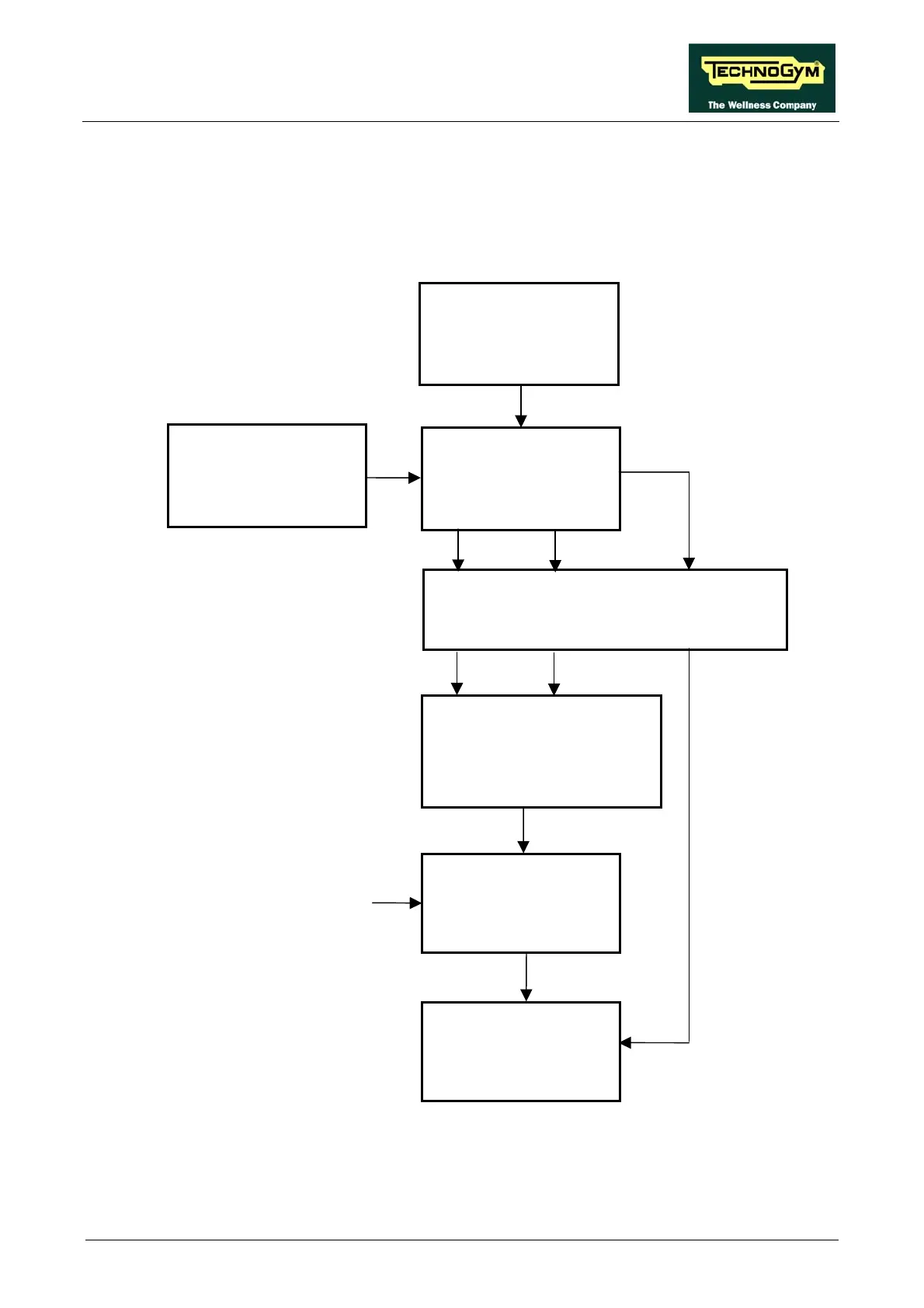
The control block diagram is as follows:
Inverter
Digital Plan Board
Elevation + Cut-out Board
Relay
Enable
Emergency
4-6/CN9
2-3/X4
R+ R-
0-1
L1-L2
Emergency
Clear
Keyboard
Contact
2-6/CN9
-
Reset
5-6/CN9
4-3/X4
~ 220 VAC
2-6
4-8
~ 220 VAC
RS-485
Download Board
Emergency
9-12/X2
Reset
10-12/X2
9-12/X1 10-12/X1
The digital plan board monitors the state of the emergency switch. As soon as the emergency is
tripped, it sends an alarm signal to the elevation + cut-out board and the commands for halting the
motors over the 485 serial link. The elevation board uses the emergency signal to energize the relay
coil which isolates the inverter power supply. when the emergency is inactive the contact is closed,
Page 3.17