RUN EXCITE: Service & Maintenance Manual - rev. 1.5
Page 6.14
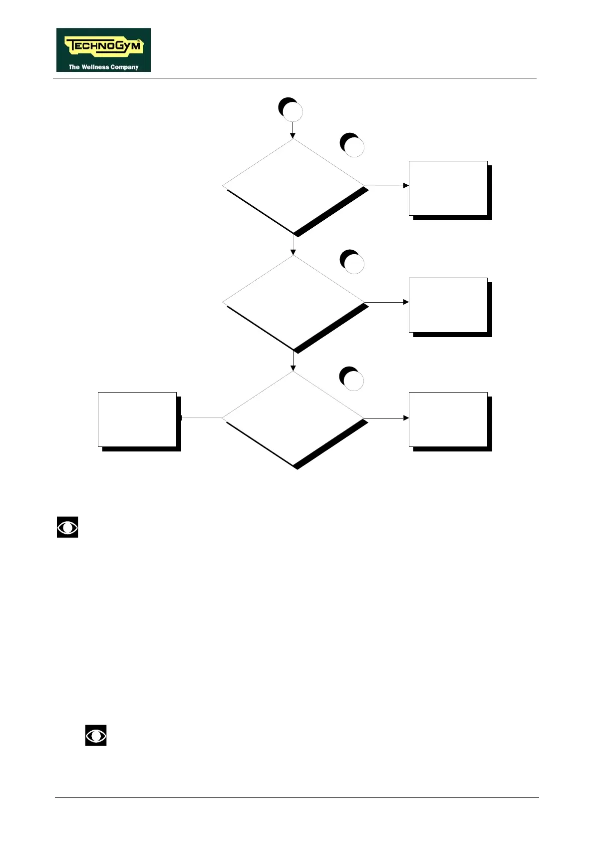
Are the DC v oltages at the
input to the LED board
correct?
Replace the LED board Replace cable TRM-24
NO
YES
14
D
Are the DC v oltages at the
input to the digital plan
board correct?
Replace cable TRM-20
Are the DC v oltages at the
output of the digital plan
board correct?
NO
YES
NO
13
Replace the digital
plan board and/or the
386 board
12
YES
Follow the procedure step by step to correctly diagnose the problem. Take particular care with the
checks highlighted by circled numbers, which are described in detail below:
To speed up the troubleshooting procedure, check the state of the power indicator LEDs
on the various circuit boards.
(1) Slightly lift the Faston connectors on the machine power inlet socket. Place the tester probes
across the live and neutral pins on the same connector. The measured voltage should be
approximately 220 VAC or 110VAC on the 110 models.
(2) As for step (1) but across the input of the circuit breaker.
(3) As for step (1) but across the output of the circuit breaker.
(4) Slightly lift the Faston connectors on the input of the filter. Place the tester probes across the
live and neutral pins on the same connector. The measured voltage should be approximately
220 VAC.
On a 110VAC model, check that the autotransformer properly generates the
220VAC input to the filter. Otherwise check and/or replace the autotransformer.