STEP EXCITE: Service & maintenance manual - rev. 1.4
Page 7.36
7.14. DISASSEMBLING THE PRIMARY SHAFT ASSEMBLY
Figure 7.14-1
Carry out the operations described in paragraph
7.7. “Disassembling the guards”.
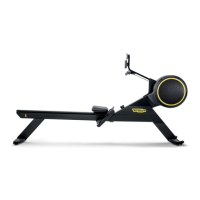
1. Remove the spring from the pin a on the
frame of the machine.
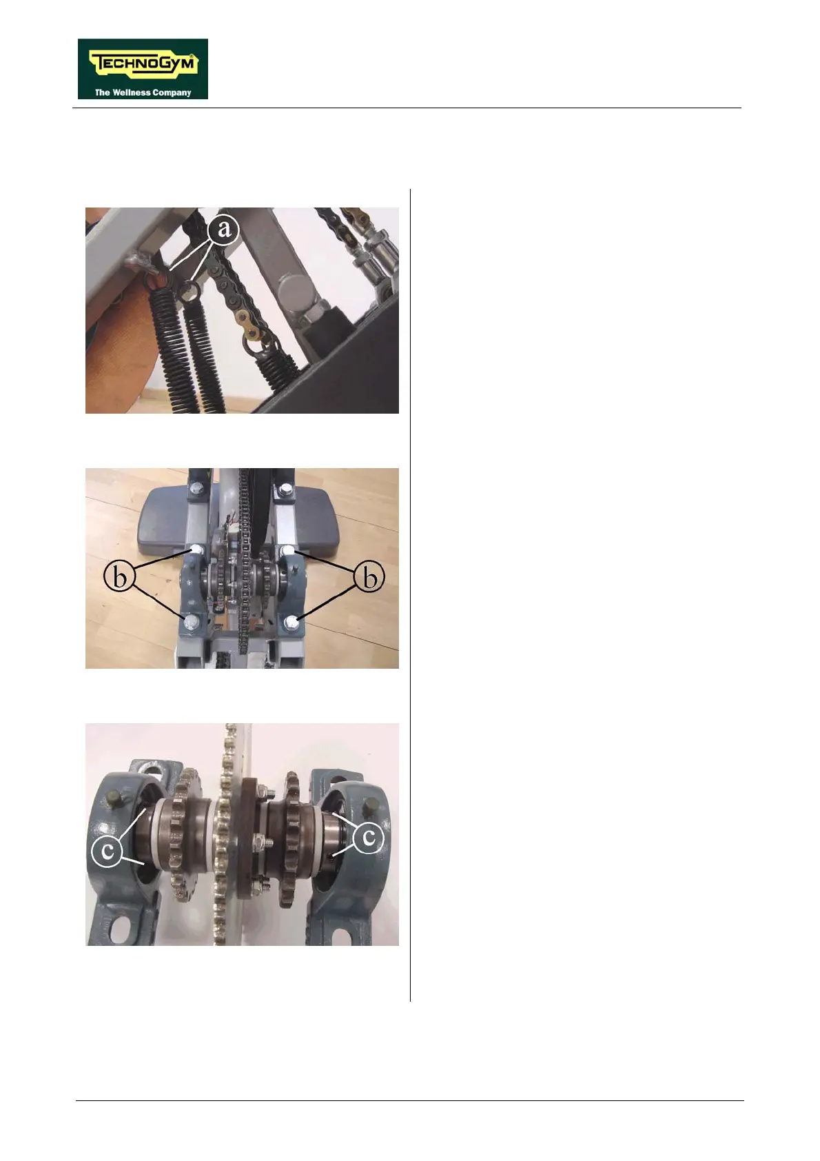
Figure 7.14-2
2. Back off the 4 screws b using a 19-mm
wrench.
3. Remove the primary shaft assembly from the
chain and place it on a work bench.
Figure 7.14-3
4. Back off the 2 grub screw c in the internal
side of the bearing using a 3-mm hex
wrench.
Continued on following page →