STEP EXCITE: Service & maintenance manual - rev. 1.4
Page 4.5
4.5.1. INSTALLATION PROCEDURE
NOTE: It is always advisable, in any case, to upgrade the brake interface board to the
latest SW version.
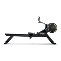
Figure 4.5-1
The upgrade kit consists of:
(1) External connector board cover plate
(cod. 0C000550AB);
(2) External connector board
(cod. 0WQ00115AC);
(3) Self-tapping screws 5x14 (cod. 0Z775);
(4) Self-tapping screws 3.5x6 (cod. 0Z7018);
(5) Washers (cod. 0Z343);
(6) Connector plate (cod. 0G000353AB);
(7) Union connector (cod. 0K000303AA);
(8) STP_07 cable (cod. 0WCU0008AA);
(9) CB-9 cable (cod. 0WC00447AB);
(10) Code sticker (cod. 0E109);
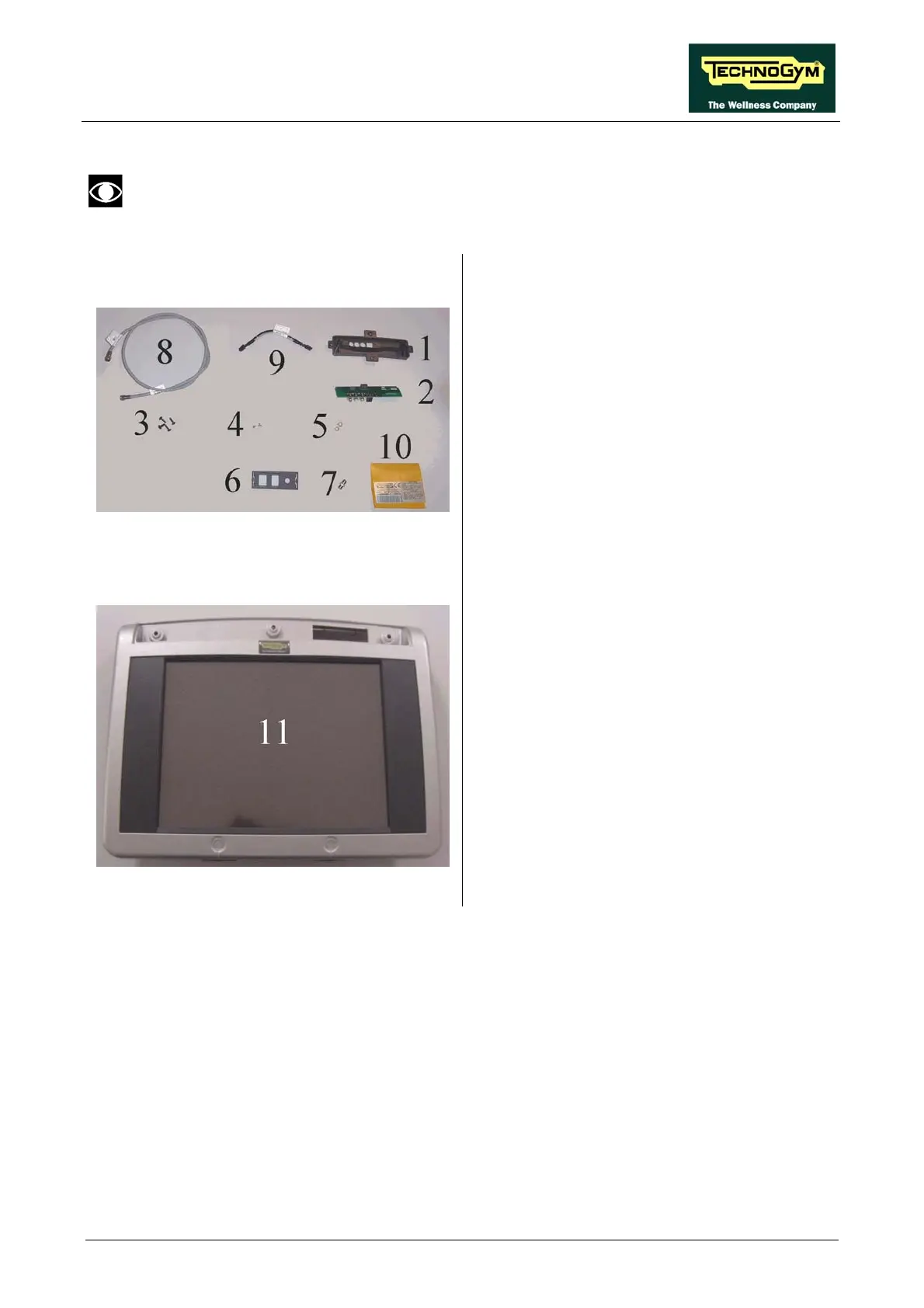
Figure 4.5-2
(11) 12-inch LCD display assembly.