STEP EXCITE: Service & maintenance manual - rev. 1.4
Page 3.11
3.2. BRAKE CONTROL
3.2.1. MECHANICS
The motion of the pedals imparts a rotation to the primary shaft via the chain connected to the 2
pedals. This chain actually consists of sections of chain coupled with springs. The primary shaft is
connected to the secondary shaft by means of a chain, which is in turn connected to the brake by
means of a belt. The speed sensor (only on mains operated models) attached to the frame detects the
heads of the screws which secure the disk to the flywheel, and generates a signal proportional to the
speed. On self powered machine, the speed value is detected measuring a phase of the alternator.
3.2.2. CONTROLS
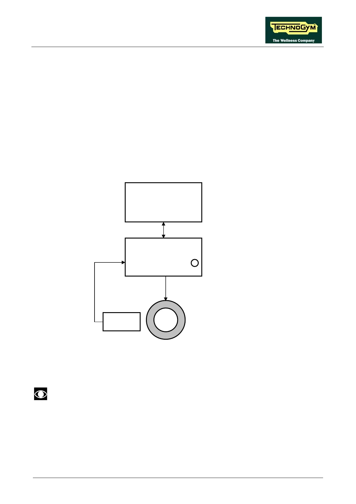
The control block diagram is as follows:
To obtain a given exercise effort level, the display board sends the required value of exercise speed
in step per minute to the Brake board via the RS-485 serial link. Based on the commands received
the brake board will then apply the appropriate excitation current to the brake winding, which
generates an electromagnetic field.
When the brake interface board receives the signal to generate resistance, the green
LED illuminates.
The electromagnetic field produced by the winding and the rotation of the disk will induce eddy
currents in the disk itself, giving rise to a force that tends to brake its motion. This generates the
exercise resistance.
A higher brake excitation signal will produce a correspondingly higher exercise resistance.
Display Board
Brake board
RS-485
CN9
CN4
1-2/CN2
Brake
Excitation Current
3-4/CN2
Pulses
Speed
sensor
Green LED