STEP EXCITE: Service & maintenance manual - rev. 1.4
Page 2.16
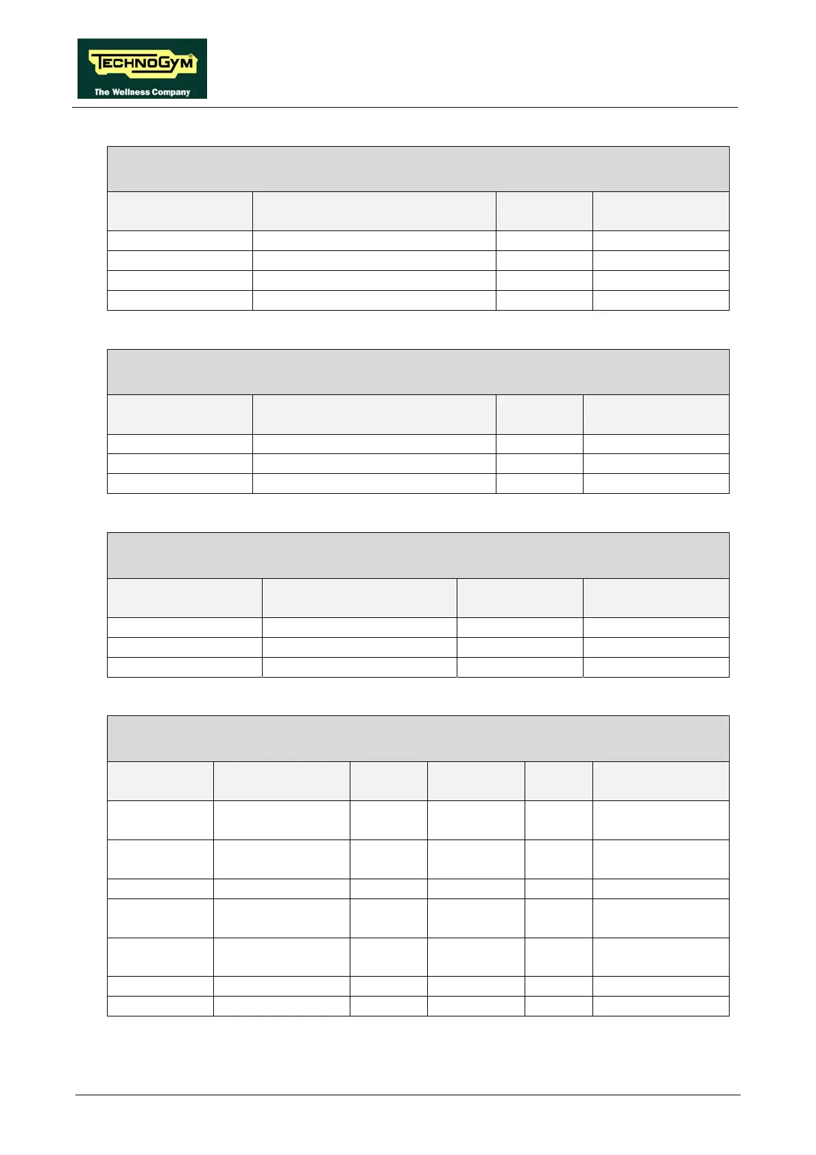
CV-302: LCD inverter power supply cable
CPU Board - LCD Inverter
CPU Board
CN5
Signal Color LCD Inverter
CN1
2 Gnd Black 2
3 +3.3 Vdc power supply Black 3
4 Gnd Black 4
5 +12 Vdc power supply Orange 5
ELT-16: HFU Receiver cable
Display Board – HFU Receiver
Display Board
CN3
Signal Color HFU Receiver
1 +5 Vdc power supply White 2
7 Pulse (beat to beat) Black 4
8 Gnd Green 1
STP-00: High voltage cable
Power entry module – Brake board
Power entry module Signal Color Brake board
CN3
F Line White 1
N Neutral Brown 3
T Earth Green 5
STP-01: Alternator cable
Brake board – Alternator – Battery – Inlet for battery charging
Brake board
CN3
Signal Color Alternator Battery Battery charging
inlet
1 V+ voltage from
alternator
Red Faston -
2 V- voltage from
alternator
Black Faston -
3 RPM signal White Faston
4 V+ voltage from
battery charger
Red - soldered to
internal contact
5 V- voltage from
battery charger
Black - soldered to
external contact
6 Battery V+ Red - Faston -
7 Battery V- Black - Faston -