Page 88 of 95
7.10-00110b_en
Options
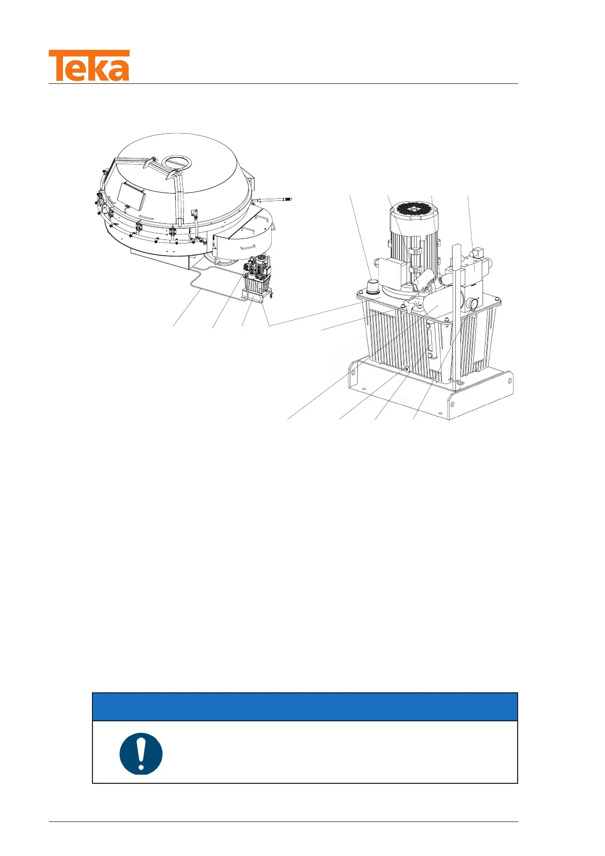
13�2�2 Unit complete with tank and directional valves
1
3
4
2
6
7
8
9
13
11
10
5
12
Fig. 64: Unit with tank and directional valves
1 Connection lines
2 Pressure gauge
3 Mounting bracket
4 Hydraulic unit with mounted directional valve
5 Screw plug
*
6 Oil lter
7 Oil drain plug
8 Oil level indicator
9 Contamination indicator
10 Directional control valve
11 PRV
12 Manual pump
13 Filler nozzle
*
has no function and should always be kept closed.
NOTE
► Please observe the enclosed operating instructions in the
supplier's documentation for this�