Error detector setups Error detector overview
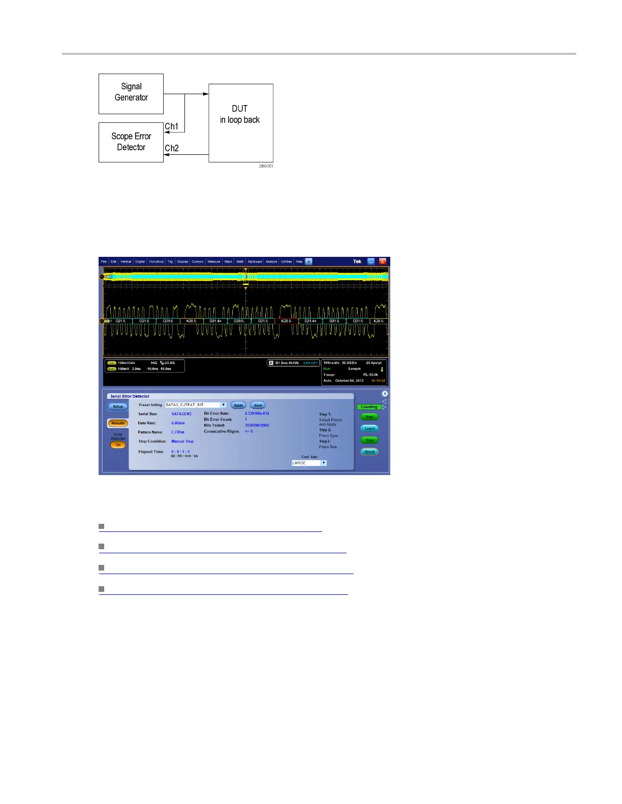
When the Error Detector is driven from the user interface, bus triggers are used whenever possible, so
that bus decoding is automatically enabled. The Decoding indicates the location of the error in the signal
by highlighting the decoded value in red, as shown in the screen c apture below. You can use additional
oscillosc
ope channels to simultaneously probe other signals to debug the cause of the error.
What do you want to do next?
Set u
p the serial error detector.
(see page 200)
Set e rror detector advanced settings. (see page 203)
Specify the error detector test pattern. (see page 204)
Set the error detector stop condition. (see page 205)
DSA/DPO70000D, MSO/DPO/DSA70000C, DPO7000C, and MSO/DPO5000 Series 207
 Loading...


