www.ti.com
Random-Number Generation
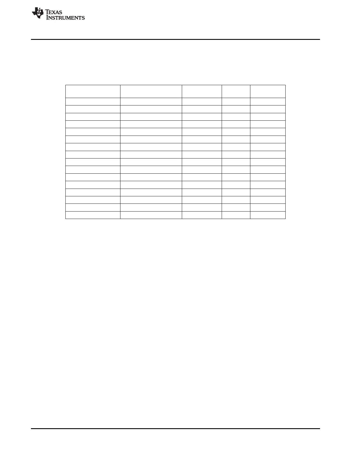
Table 23-3 shows the mapping from FSM state to the number which can be read from the FSMSTAT0
register. Note that although it is possible to read the state of the FSM, this information should not be used
to control the program flow in the application software. The states may change very quickly (every 32-MHz
clock cycle), and an 8-MHz SPI is not able to capture all the activities.
Table 23-3. FSM State Mapping
State Name State Number, Decimal Number, Hex TX_ACTIV RX_ACTIVE
E
Idle 0 0x00 0 0
RX calibration 2 0x02 0 1
SFD wait 3–6 0x03–0x06 0 1
RX 7–13 0x07–0x0D 0 1
RX/RX wait 14 0x0E 0 1
RXFIFO reset 16 0x10 0 1
RX overflow 17 0x11 0 0
TX calibration 32 0x20 1 0
TX 34–38 0x22–0x26 1 0
TX final 39 0x27 1 0
TX/RX transit 40 0x28 1 0
ACK calibration 48 0x30 1 0
ACK 49–54 0x31–0x36 1 0
ACK delay 55 0x37 1 0
TX underflow 56 0x38 1 0
TX shutdown 26, 57 0x1A, 0x39 1 0
23.12 Random-Number Generation
The RF Core can generate random bits. The chip should be in RX when generation of random bits is
required. One must also make sure that the chip has been in RX long enough for the transients to have
died out. A convenient way to do this is to wait for the RSSI-valid signal to go high.
Single random bits from either the I or Q channel can be read from the register RFRND.
Randomness tests show good results for this module. However, a slight dc component exists. In a simple
test where the RFRND.IRND register was read a number of times and the data grouped into bytes, about
20 million bytes were read. When interpreted as unsigned integers between 0 and 255, the mean value
was 127.6518, which indicates that there is a dc component.
The FFT of the first 2
14
bytes is shown in Figure 23-21. Note that the dc component is clearly visible. A
histogram (32 bins) of the 20 million values is shown in Figure 23-22.
247
SWRU191C–April 2009–Revised January 2012 CC253x Radio
Submit Documentation Feedback
Copyright © 2009–2012, Texas Instruments Incorporated

 Loading...


