EasyManuals Logo

Texas Instruments mmWaveICBoost User Manual

Texas Instruments mmWaveICBoost
80 pages
To Next Page IconTo Next Page
To Previous Page IconTo Previous Page
Page #38 background imageLoading...
Page #38 background image
xWR6843ISK / IWR6843ISK-ODS REV C
www.ti.com
38
SWRU546COctober 2018Revised April 2020
Submit Documentation Feedback
Copyright © 2018–2020, Texas Instruments Incorporated
mmWaveICBoost and Antenna Module
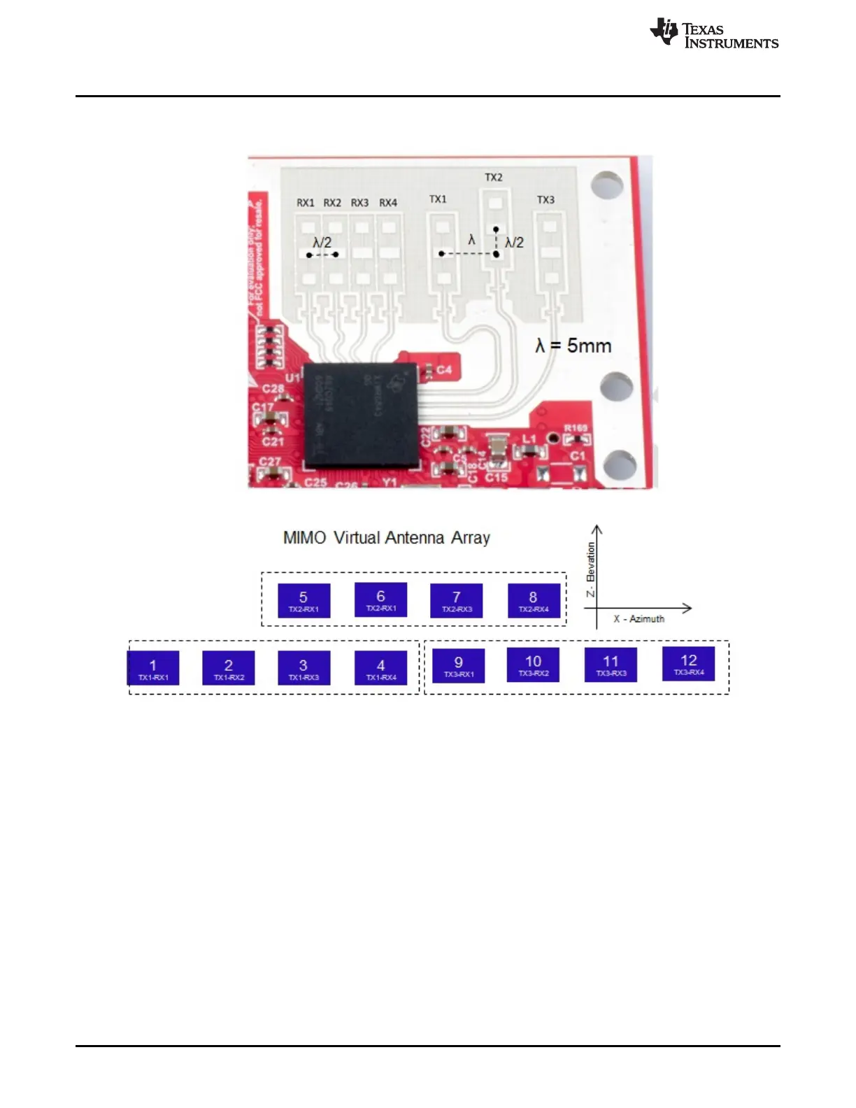
Figure 42. IWR6843ISK antenna placement MIMO array
Figure 43 through Figure 45 shows the antenna radiation pattern with regard to azimuth. Figure 46
through Figure 48 show the antenna radiation pattern with regard to elevation for TX1, TX2, and TX3.
All of the measurements were done with a Tx and Rx combination together. Thus, for the -6dB beam
width, you must see a -12db (Tx (-6dB) + Rx(-6dB)) number.

Table of Contents

Questions and Answers:

Question and Answer IconNeed help?

Do you have a question about the Texas Instruments mmWaveICBoost and is the answer not in the manual?

Texas Instruments mmWaveICBoost Specifications

General IconGeneral
BrandTexas Instruments
ModelmmWaveICBoost
CategoryMotherboard
LanguageEnglish

Related product manuals