HYDRAULICS
8E-21
SECTION 8E. FRONT AND REAR TRACTION MOTORS
TRACTION CIRCUIT
The traction circuit is a parallel/series circuit in which
the oil being delivered by the traction pump to the front
wheel motors is divided between the left and right
motors (parallel). This allows the wheel motors to
speed up or slow down independently to enable turn-
ing. The oil, once through the front wheel motors, goes
directly to the rear wheel motors (series). This results in
improved traction, as both the front and rear wheel on
one side must break traction in order for the drive to
stop moving the tractor, as oil will follow the path of
least resistance.
The rear wheel motors are equipped with directional
check valves that close when moving forward and open
for reverse. The result is four-wheel drive when travel-
ing forward and an automatic shift to two-wheel drive
when in reverse.
The traction circuit on four-wheel drive units is addition-
ally equipped with a hot oil shuttle. The hot oil shuttle
drains off hot oil from the closed loop traction circuit
back to the reservoir. The drained-off oil is replenished
with cooler oil in the circuit by the charge pump in the
traction pump. The hot oil shuttle opens when traveling
forward and closes when in reverse direction.
On two-wheel drive models the traction circuit can be
equipped with an optional differential lock valve. The
differential lock valve is essentially a flow divider
installed between the traction pump and the front wheel
motors. When activated, the flow divider equally splits
the amount of oil flow from the traction pump to the
front wheel motors so that they turn at the same speed.
The flow divider hinders left and right turns when acti-
vated.
IMPORTANT: In general, when a component failure
occurs in the traction circuit, such as a traction pump or
wheel motor, the closed loop circuit of the traction
pump may become contaminated with metal particles
which could damage expensive new replacement
components. In a situation where contamination has
occurred, the closed loop circuit must be pressure
filtered in both the forward and reverse directions for at
least 20 minutes using the Portable In-Line Filter
#JAC5097. Failure to filter the system will contaminate
and destroy new replacement components.
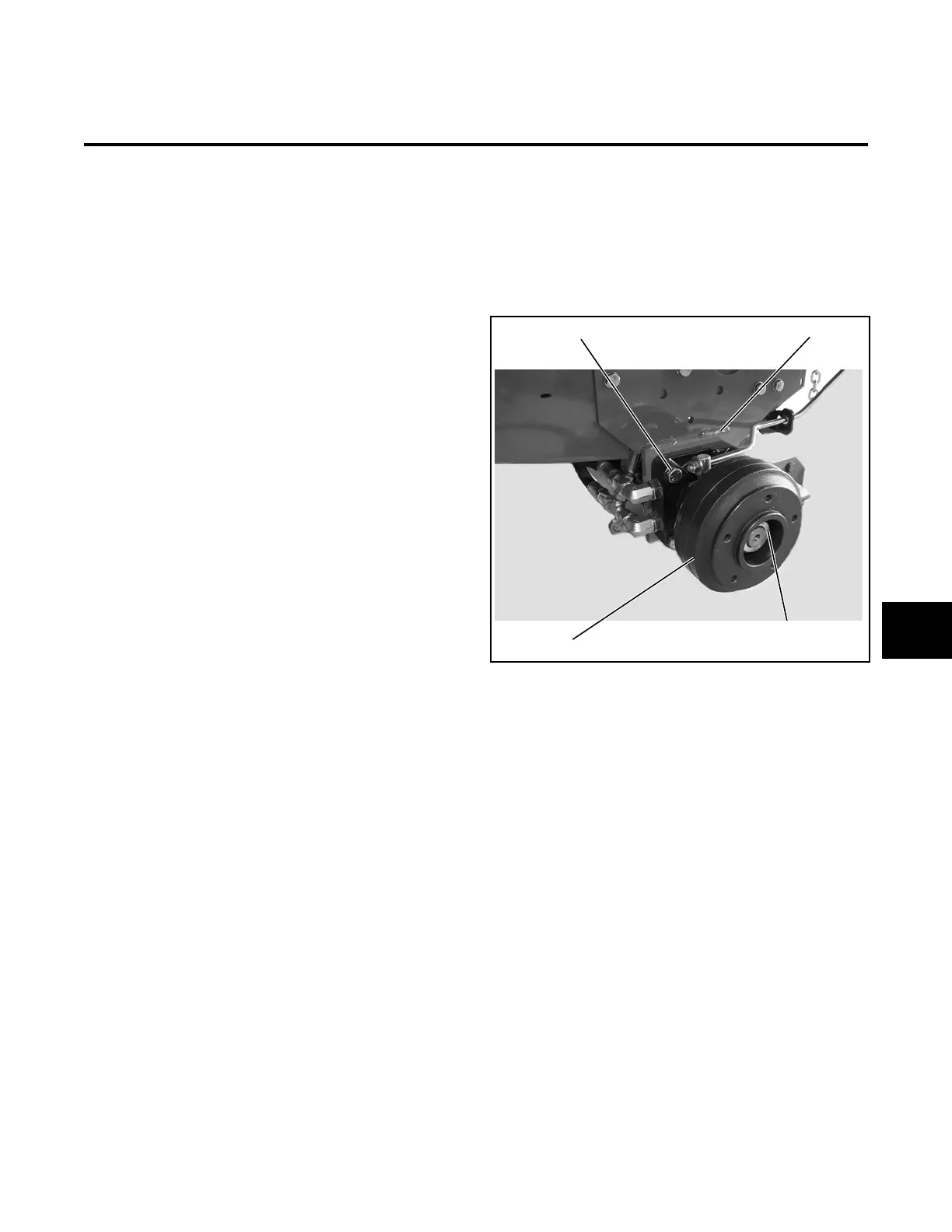
FRONT TRACTION MOTOR
The traction pedal and traction pump control the front
traction motors. The motor is mounted to the tractor
frame inside the front wheel mounting. The brake drum
is attached to the motor shaft end and serves as the
wheel mounting.
Figure 8E-1. Brake Drum and Traction Motor
Mounting
Removal
1. Shut off engine and remove ignition key.
2. Using jack stands, lift and support the front axle.
3. Remove the wheel and tire assembly.
4. Remove the brake drum nut, brake drum, brake
shoes, and backing plate (Section 5).
5. Thoroughly clean the motor, especially the area
surrounding the hydraulic fittings.
6. Tag and disconnect the hydraulic hoses from the
motor. Immediately plug the hoses and motor to
prevent contamination of the hydraulic system.
7. While supporting the motor, remove the four
mounting bolts.
8. Remove the motor from the tractor frame.
Brake Drum Nut
Tractor FrameMounting Bolts
Brake DrumBrake Drum
8E
 Loading...


