CONTROLS
2C-7
4. Once obtained, hold the adjusting nut with a
wrench and tighten the jam nut against the adjust-
ing nut to lock the adjustment in place.
5. With the traction pedal in the locked neutral posi-
tion (pedal latch up), adjust the cable length at the
cable retaining nuts so that the retaining bolt at the
ball joint aligns with the hole in the traction pedal.
6. Connect the cable to the traction pedal and secure
with the nut.
MAXIMUM TRANSPORT SPEED
The traction pedal should always contact the stop bolt
(Figure 2C-5). If the traction pedal will not contact the
stop bolt, the stop bolt should be adjusted so that it
contacts the traction pedal to prevent damage to the
hydrostatic pump and control linkage.
Figure 2C-5. Traction Pedal
Before making speed adjustments at the pump, check
that the engine is running at full rpm under load and the
throttle is adjusted correctly.
Cutting quality is better at speeds well below the trans-
port speed of the tractor. Local turf conditions may
respond better to different speeds.
To adjust the maximum forward transport speed,
loosen the jam nut and adjust the stop screw
(Figure 2C-5) up to reduce speed or down to increase
speed.
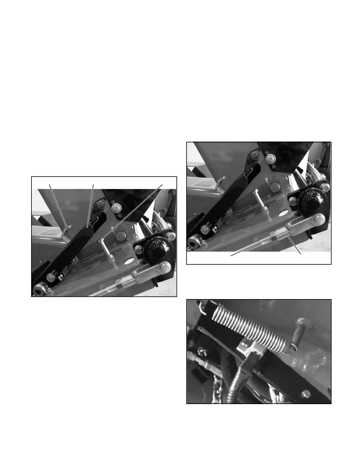
PARKING BRAKE
Adjust the parking brake (Figure 2C-6) after replacing
or servicing the brake assembly, or if pedal travel
becomes excessive.
1. After installing new brake pads, burnish the shoes
by driving the tractor at mowing speed while
applying slight pressure on the brake pedal for
approximately five seconds. Release and repeat
five times.
2. Loosen the upper brake rod end yoke jam nut on
both sides. (Figure 2C-6).
Figure 2C-6. Parking Brake
3. Disconnect the brake return spring (Figure 2C-7)
at the pedal mechanism.
Figure 2C-7. Brake Return Spring
4. Remove the cotter pin and pin from the end yokes.
Pedal Latch Traction Pedal
Stop Bolt
 Loading...


