HYDRAULICS
8D-20
Control Group Assembly
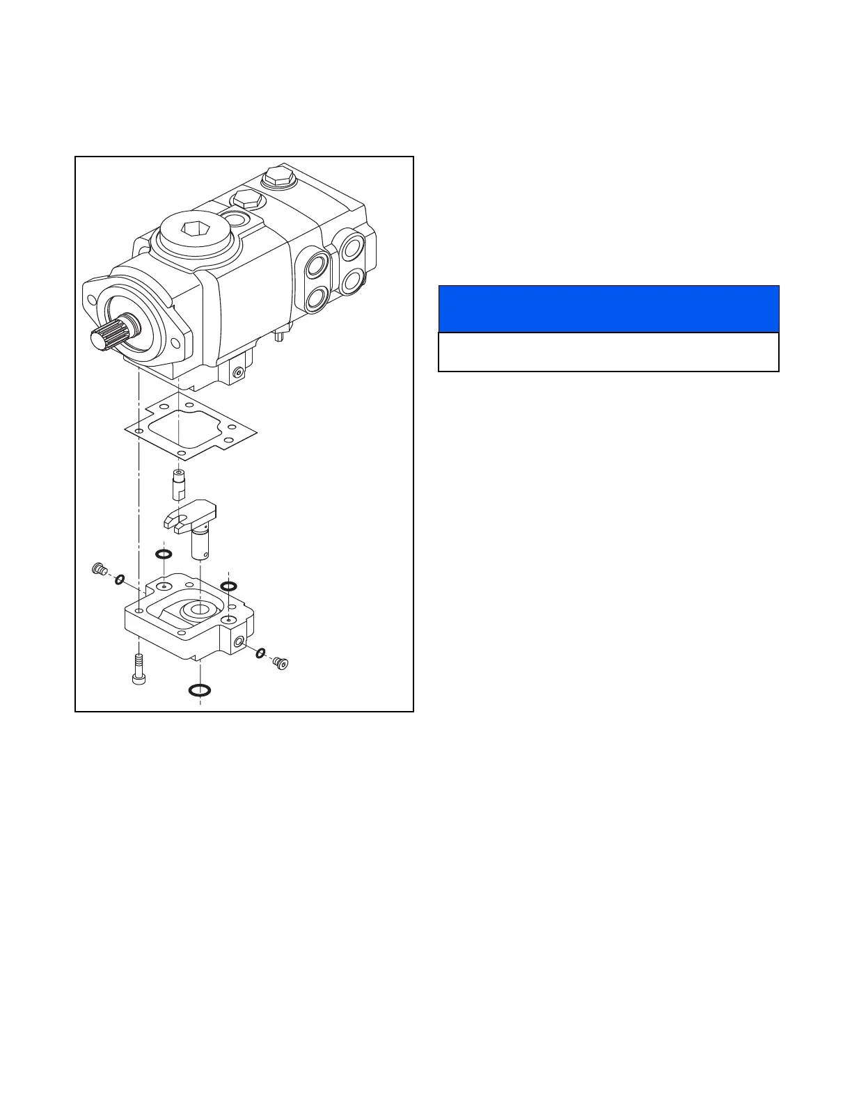
See Figure 8D-16 for control group assembly.
Figure 8D-16. Control Group Assembly
INSTALLATION
1. Using a new o-ring lubricated with clean hydraulic
oil, position the implement pump on the traction
pump and secure with two hex-head cap screws.
2. Place the traction pump/implement pump in the
frame, align the traction pump spline shaft and
insert to the face of the bell housing (Figure 8D-5).
Secure with two hex-head mounting bolts and
washers.
3. Using tags created during disassembly, remove
the plugs and connect the hoses to the traction
pump and the deck pump.
4. Replace the hydraulic oil filter and fill the hydraulic
tank with hydraulic oil.
5. Pivot the seat and seat platform to the lower posi-
tion for normal operation. Latch into position.
6. Start the engine and check the component opera-
tion. If necessary, perform the tests and checks
described in Section 8L.
Gasket
Control Pin
O-Ring
Control
Housing
O-Ring
Arm and Pintle
Traction Pump
Assembly
NOTICE
Refer to Section 4C for positioning and installation of
traction pump coupling.
 Loading...


