HYDRAULICS
8D-11
SECTION 8D. HYDROSTATIC TRACTION PUMP
GENERAL
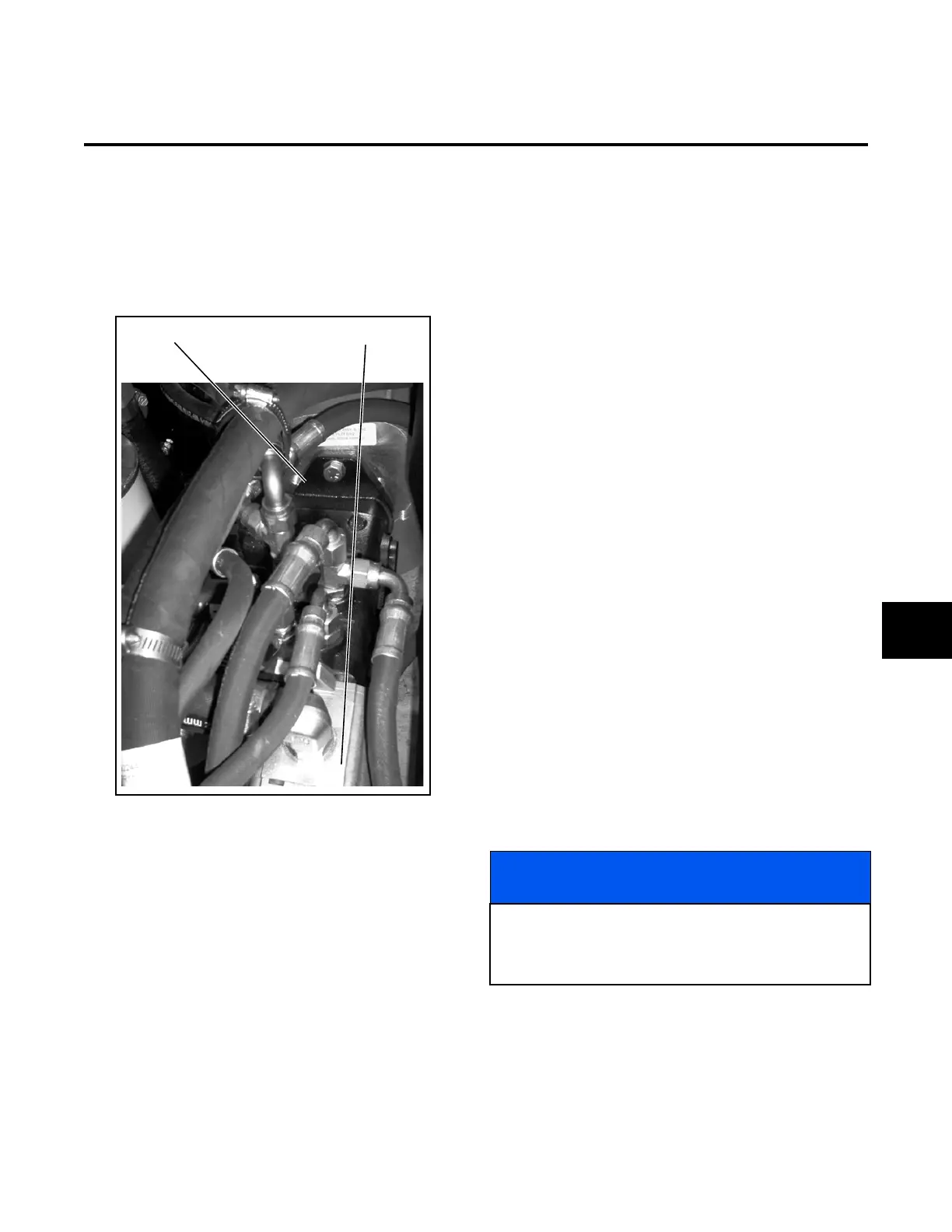
The hydrostatic traction pump (Figure 8D-1) is
mounted underneath the seat pan and in front of the
engine. The pump is driven by the engine through a
spline shaft direct coupling. The traction pump is bolted
to a bell housing.
Figure 8D-1. Traction Pump/Implement Pump
The hydrostatic traction pump consists of two pumps
(Figure 8D-2). The 0.425 cu. in. gerotor pump supplies
oil to the steering, lift, and charge circuits. The charge
circuit charges the traction pump and circuit with oil.
The second, a 1.35 cu. in. piston pump, supplies oil to
the traction circuit.
A set of eight pistons and barrel assembly produce
pump suction and pressure. The pistons have shoes
that ride against a swiveling swashblock. By swiveling
the swashblock, the piston stroke is extended on one
side of the barrel assembly and shortened on the other
side. The extended piston stroke produces hydraulic
pressure, which is directed to one side of the wheel
traction motors, turning the motors and attached
wheels. Oil passes through the motor and returns to
the traction pump.
When the swashblock is swiveled in the opposite direc-
tion, oil flows to the opposite side of the traction motors
turning the motor and attached wheels.
The direction of the swashblock swivel is controlled by
the traction pedal and pump control arm.
A supercharge pump is mounted between the rotating
group and rear valve plate assembly. The pump draws
fluid from the hydraulic tank and supplies hydraulic
pressure to the steering unit and the traction circuits
through the cross port relief valves.
Repair of the traction pump is limited to replacement of
the various pump group service kits. These kits are
illustrated and defined by part numbers in the parts
section of the Parts & Maintenance Manual.
Before disassembling the traction pump (Figure 8D-3),
perform the hydraulic tests in Section 8M to verify that
the pump is at fault.
Disassemble only what is necessary to facilitate
needed repairs. Use the following procedure taking
note of special instructions. If possible, do not remove
locator pins. Discard and replace all o-rings, backup
rings, and gaskets.
Disassembly should be in an area free of dust, dirt and
away from grinding and welding areas. Keep parts in a
bath of clean hydraulic fluid.
Traction Pump
Implement Pump
NOTICE
The system must be high pressure filtered after any
repairs to the traction pump or motor. A suitable high
pressure filter such as the Jacobsen 5097 is recom-
mended.
8D
 Loading...


