ATTACHMENTS
12E-28
5. Tag and disconnect the hydraulic hoses from the
deck valve. Immediately plug the hoses and deck
valve to prevent contamination of the hydraulic
system.
6. Tag and disconnect the case drain hose from the
drive motor. Immediately plug the hose and motor
port to prevent contamination of the hydraulic sys-
tem.
7. Remove safety clips and pins (Figure 12E-3) from
both push arms and hanger brackets.
Figure 12E-3. Push Arm Mounting
8. The flail mower can now be moved away from the
tractor or the tractor backed away from the mower.
INSTALLATION
1. Place the mower squarely in front of the tractor
front wheels.
2. Using tags created during removal, remove plugs
and connect case drain hose to the drive motor.
3. Using tags created during removal, remove plugs
and connect hoses to the deck valve (Figure 12E-
2).
4. Position the front pivot of the push arms
(Figure 12E-3) inside the mower hanger brackets.
Insert the pins through the brackets and push
arms. Secure the pins with safety clips.
5. Align the safety/lift chains with the mower brack-
ets. Secure the chains to the deck with bolts,
washers, and nuts.
6. Start engine and raise the mower completely.
Attach the weight transfer springs to the upper
anchor bolts. Lower the mower.
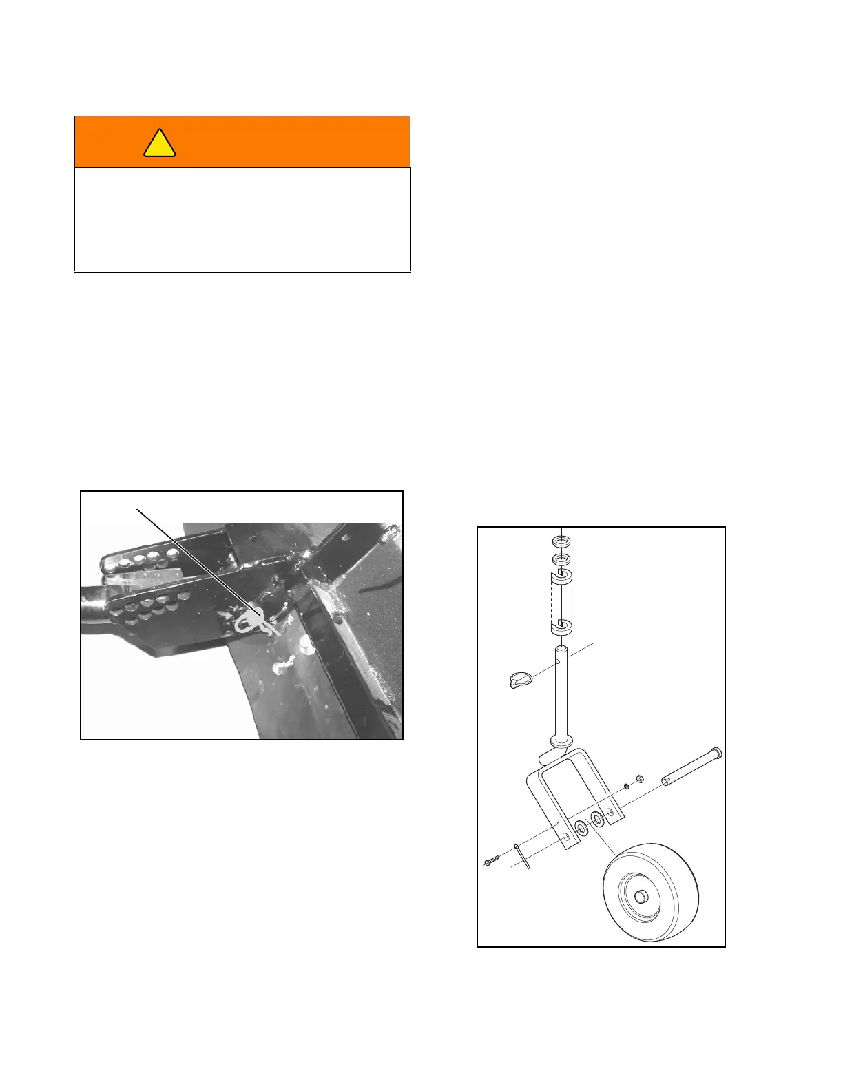
CASTER WHEELS
The two caster wheels are mounted on the front of the
flail mower frame. The wheels can be removed,
inspected, and installed using Figure 12E-4.
Maintain air pressure in caster tires at 22-24 psi (152-
165 kPa) to maintain cutting height. Check air pressure
while tires are cool. Inflate tires equally to maintain cut-
ting height from side to side.
Figure 12E-4. Caster Wheel
WARNING
Never open or loosen hydraulic lines under pres-
sure. Hydraulic fluid escaping under pressure can
have sufficient force to penetrate skin. If fluid is
injected into the skin it must be surgically removed
within a few hours by a doctor familiar with this form
of injury, or gangrene may result.
 Loading...


