STEERING
6C-9
12.Remove the face seal (20) and seal spacer (22).
13.Remove the thrust bearing (19) and spacer (18).
14.Remove the upper cover plate (23) and retaining
ring (24).
15.Remove the special bolts (25).
16.Remove the steering shaft (26) out of tube (27).
17.Remove the bushing (28) and seal (29).
STEERING VALVE INSPECTION
1. Inspect the springs (7 and 10) for bent, broken, or
distorted coils.
2. Inspect the finished ground surfaces of all the
components.
3. Inspect the slot edges and surface for nicks, scor-
ing, and rounding.
4. Inspect the hex drive (11) for wear.
5. Inspect the isolation manifold (13) for nicks,
scratches, and scoring. A polished wear pattern
due to valve plate rotation is normal.
6. Inspect the drive link (14) for wear and damage.
7. Inspect the thrust bearing (19) for brinelling, spal-
ling, and missing rollers.
8. Discard all seals and seal rings.
9. Inspect the commutator cover (2) and drive plate
(9) for wear and damage. A polished wear pattern
is normal (Figure 6C-4).
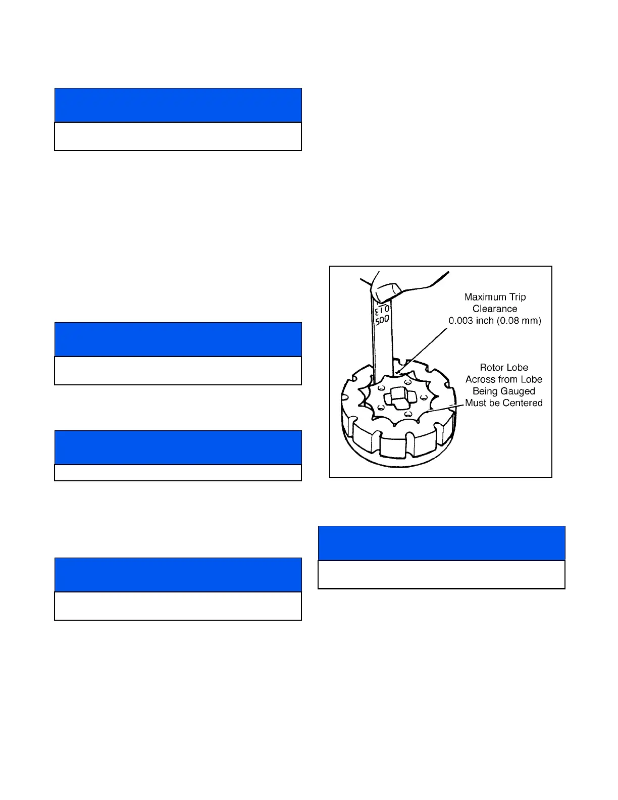
10.Inspect the rotor (7) and stator (8) fit
(Figure 6C-5.)
Figure 6C-5. Rotor and Stator Inspection
STEERING VALVE ASSEMBLY
1. Install a new seal (29) and bushing (28) in the
tube (27). Crimp the tube and end in two places,
90° apart.
2. Place the tube (27) and special bolts (25) in the
service fixture.
NOTICE
The following steps reference Figure 6C-3 unless
otherwise noted.
NOTICE
The following steps reference Figure 6C-3 unless
otherwise noted.
NOTICE
Always replace springs as a set.
NOTICE
The valve ring (8) and valve plate (9) are a matched
set and are not serviceable.
NOTICE
The following steps reference Figure 6C-3 unless
otherwise noted.
 Loading...


