ATTACHMENTS
12E-31
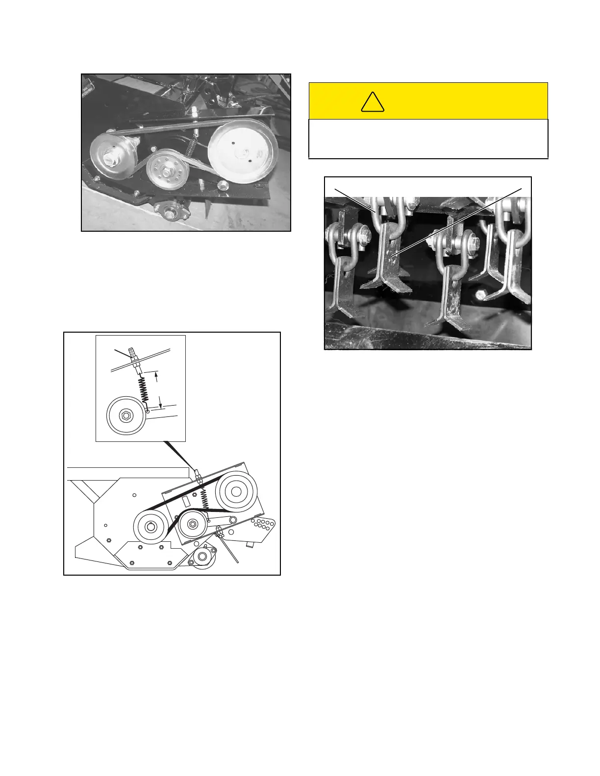
Figure 12E-8. Drive Belt
1. To replace belt, remove belt cover, loosen hex
nuts (A, Figure 12E-9) to relieve belt tension.
Install new belt as shown.
2. Adjust spring to dimensions (B) 4 ± 1/16 inches
(102 ± 1.6 mm).
Figure 12E-9. Drive Belt Adjustment
3. Install drive belt cover.
FLAIL BLADE INSPECTION
Every 50 hours, or whenever mower is removed from
tractor, carefully inspect the shackles (C, Figure 12E-
10) and blades (D) to be sure they are in good operat-
ing condition.
Figure 12E-10. Shackles and Blades
1. Remove any debris wound around the rotor.
2. If one edge of a double edged blade is worn,
remove blades (D), turn them 180° and assembly
to rotor with cutting edge facing forward.
3. If all blades are worn on one side only, the entire
rotor can be removed and turned 180°.
a. Remove drive belt cover, drive belt and rotor
pulley.
b. Remove bumper guard, remove skid shoes
and rotor bearing mounting bolts from both
sides of housing.
c. Slide the rotor out of the housing (bearings do
not have to be removed), turn rotor 180°, and
slide rotor into housing.
4. Carefully assemble rotor and components. The
rotor must be centered with the housing. Grease
the fittings on both rotor bearings face and the top
of housing.
DRIVE MOTOR REMOVAL
The drive motor (Figure 12E-11) can be removed by
removing the drive belt cover.
B
A
CAUTION
Operating the mower with missing or damaged parts
can cause severe vibration and damage to other
components.
 Loading...


