ATTACHMENTS
12D-8
REMOVAL
1. Start the engine and raise the deck completely.
Figure 12D-2. Weight Transfer Springs
2. Disconnect the weight transfer springs from the
upper anchor bolts (Figure 12D-2).
3. Lower the deck.
4. Engage parking brake, disengage all drives, shut
down the engine, and remove the ignition key.
5. Disconnect the safety/lift chains (A) from the
mower deck.
Figure 12D-3. Deck Valve
6. Tag and disconnect the hydraulic hoses from the
deck valve (B). Immediately plug the hoses and
deck valve to prevent contamination of the
hydraulic system.
7. Tag and disconnect the case drain hose from the
drive motor. Immediately plug the hose and motor
port to prevent contamination of the hydraulic sys-
tem.
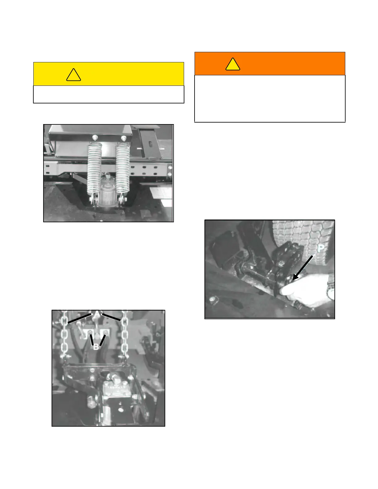
8. Remove bolts, nuts and pins (P, Figure 12D-4)
from both push arms and deck hanger brackets.
Figure 12D-4. Push Arm Mounting
9. The mower deck can now be moved away from
the tractor or the tractor backed away from the
deck.
INSTALLATION
1. Place the deck square and approximately 2” in
front of the tractor front wheels.
2. Using tags created during removal, remove plugs
and connect case drain hose to the drive motor.
3. Using tags created during removal, remove plugs
and connect hoses to the deck valve
(Figure 12D-3).
CAUTION
Allow hydraulic components to cool completely
before removal from the tractor.
WARNING
Never open or loosen hydraulic lines under pres-
sure. Hydraulic fluid escaping under pressure can
have sufficient force to penetrate skin. If fluid is
injected into the skin it must be surgically removed
within a few hours by a doctor familiar with this form
of injury, or gangrene may result.
 Loading...


