ATTACHMENTS
12E-30
The rear roller can be adjusted by inserting the bolts
into one of six holes. Use the Table 12E-1 (column #3)
for bolt placement. The bolts must be inserted into the
same holes on both sides of the mower.
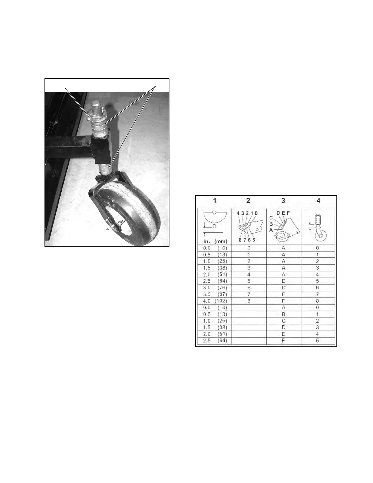
Figure 12E-7. Caster Wheel Adjustment
Spacers (Figure 12E-7) on the top and bottom of the
caster wheel spindle can be rearranged to provide
more or less caster wheel height. Use Table 12E-1
(column #4) for spacer placement.
Table 12E-1 shows the height adjustment decal used
on the flail mower. Determine the type of adjustment
desired, select cutting height, and follow across the
table to make appropriate adjustment. Metric equiva-
lents are given for reference and are not listed on decal
attached to flail mower.
• Column 1 – Height of cut
• Column 2 – Push arm adjustment
• Column 3 – Rear roller adjustment
• Column 4 – Arrangement of spacers
Examples of cutting height adjustments:
Example: 2-inch (50 mm) height of cut – rear roller
slightly raised
1. Locate height of cut in Table 12E-1.
2. Position push arm adjustment pin in hole 4.
3. Adjust rear roller in hole (A).
4. Place four spacers on bottom of caster wheel
spindle as shown. Store remaining spacers and
washers on top portion of spindle.
Example: 1 –inch (15 mm) height of cut – rear roller on
ground
1. Locate height of cut in Table 12E-1.
2. Position push arm adjustment pin in hole 4.
3. Adjust rear roller in hole (A).
4. Place four spacers on bottom of caster wheel
spindle as shown. Store remaining spacers and
washers on top portion of spindle.
Table 12E-1: Height of Cut
DRIVE BELT
Keep the drive belt and pulleys clean. Belt is self-
adjusting. Inspect belt periodically and replace if worn
or frayed.
 Loading...


