HYDRAULICS
8H-46
3. After removing tie bolts, disassemble motor as
shown in Figure 8H-1.
4. Place parts in assembly order on a clean work
area as they are removed.
5. Discard seals as they are removed.
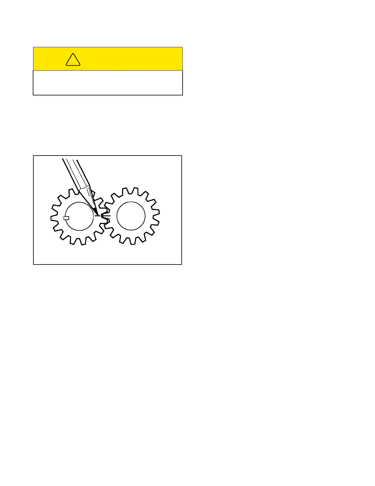
Figure 8H-2. Marking Gear Teeth
Inspection
1. Keeping parts in assembly order, clean and air dry
each for inspection. Look for metal chips or slivers
during cleaning (an indication of damage to motor
or other hydraulic components).
2. Inspect all parts for cracks, nicks, burrs, and
excessive wear. Replace entire motor if found
damaged or worn.
Reassembly
1. Apply a coat of clean hydraulic oil to all parts to
ease assembly.
2. Assemble motor one section at a time, building up
from flange section (Figure 8H-1).
3. Use a new seal kit during assembly. Use clean
grease to keep seals in position.
4. Remove alignment mark from gear sets after they
have been installed with teeth in mesh.
5. Rotate drive shaft after assembling each section
to make sure there is no binding between parts.
6. Use extreme care when installing shaft seal. It
must seat squarely in seal bore. Use the double
end seal. Use clean grease on shaft and put tape
over keyway to avoid cutting seal during assem-
bly.
7. Install the bolts finger-tight and rotate drive shaft
to make sure it turns freely. Tighten the bolts
evenly and in steps to a final torque of 37 ft-lbs
(50 N-m).
INSTALLATION
1. Install deck motor onto deck with two retaining
bolts.
2. Install pulley onto deck motor shaft.
3. Install all brackets around the deck motor and
secure with retaining bolts.
4. Align pulley on deck motor shaft and secure.
5. Install deck belt on pulley and tension belt to
proper tension.
6. Connect previously tagged hoses to the proper fit-
tings and tighten.
CAUTION
Never pry motor sections apart, as damage to seal-
ing areas can result. Use of a soft face hammer to
tap sections apart is recommended.
Marker
Mark alignment mark across meshing
teeth before disassembly.
 Loading...


