ENGINE
3D-17
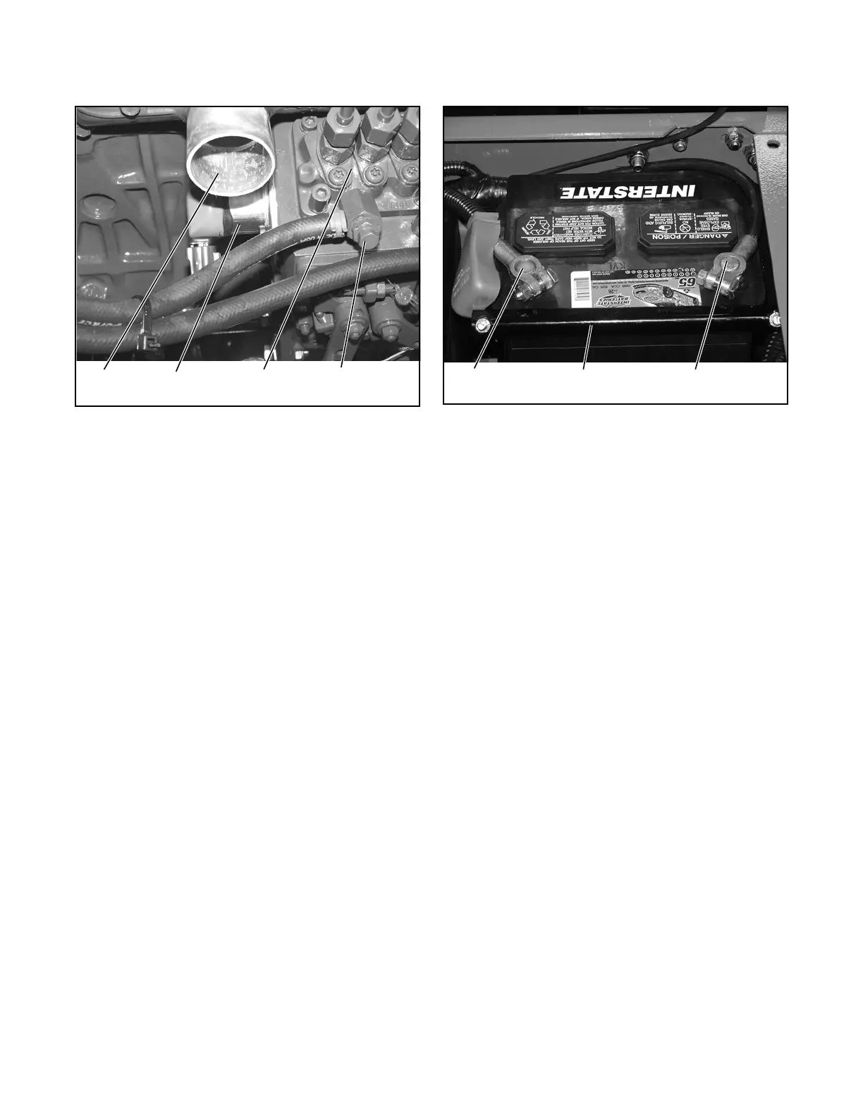
Figure 3D-16. Injection Pump Air Vent
18.Operate the primer button on top of the fuel/water
separator to fill the fuel lines with fuel.
19.Allow fuel to flow from the injection pump vent until
air bubbles no longer appear. Tighten the air vent
plug (Figure 3D-16).
20.Inspect the fuel filter, hoses, clamps, and pipes for
leaks. Repair as necessary.
ENGINE REMOVAL
The engine is mounted behind the driver’s seat and
drives the traction pump using the drive coupler. Some
components can be serviced or removed using proce-
dures previously described in this section.
1. Shut down the engine and remove the ignition
key. Allow the engine to cool completely before
attempting to service the engine.
2. Disconnect the negative battery clamp first, then
remove the positive clamp. Remove the battery
hold down clamp and battery (Figure 3D-17).
Figure 3D-17. Battery Cables and Clamp
3. Using suitable containers, drain the radiator,
engine block, engine oil and hydraulic oil.
4. Remove the upper and lower radiator hoses.
5. Tag and disconnect the hydraulic inlet and outlet
hoses from the oil cooler. Immediately plug the
hoses and cooler ports to prevent contamination
of the hydraulic system.
6. Remove the air cleaner assembly hoses.
7. Remove the radiator/oil cooler assembly
8. Drain the fuel tank.
9. Disconnect the fuel outlet hose from the fuel tank
to the inline filter. Immediately plug the hose to
prevent contamination.
10.Disconnect the throttle cable from the injection
pump and the throttle cable housing from the
clamp (Figure 3D-18).
Fresh Air
Intake
Fuel
Solenoid
Injection
Pump
Air Vent
Plug
Positive
Cable
Battery
Clamp
Negative
Cable
 Loading...


