HYDRAULICS
8M-63
Conclusion
• If gauge reading is within specification at both high
and low idle positions, pump and relief valve are
okay.
• If pressure gauge reading is within specification at
high idle and out of specification at low idle, perform
flow test on implement pump.
• If pressure gauge reading is out of specification and
pressure is the same at both high and low idle,
repair or replace deck relief valve.
Deck Relief Valve
1. Shut off the engine.
2. Drain hydraulic fluid from the tank.
3. Lift seat platform.
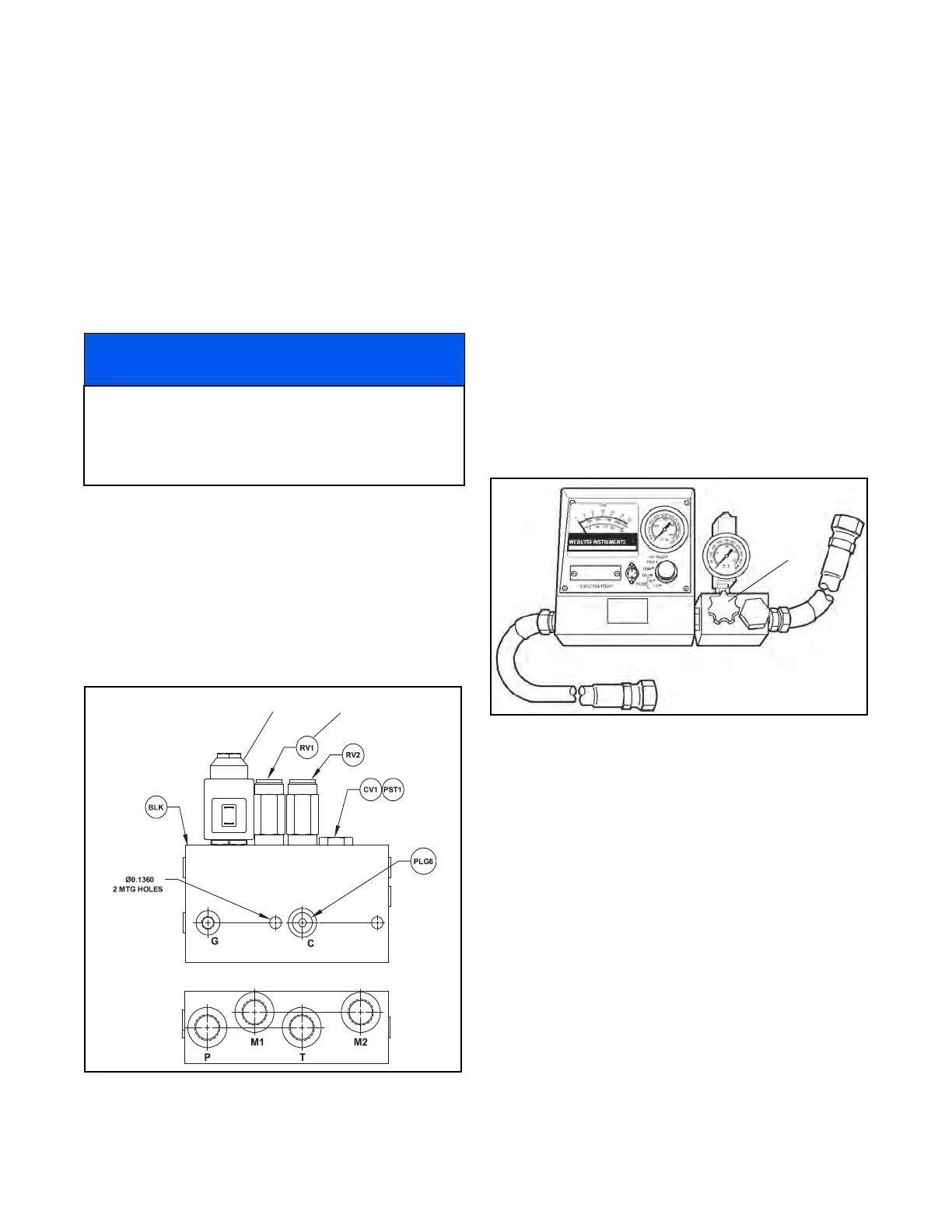
4. Remove solenoid coil from cartridge on the deck
valve (Figure 8M-12).
Figure 8M-12. Deck Relief Valve
5. Using a socket, remove the relief valve (RV1) from
the deck valve. Replace seals or relief valve as
required.
6. Install relief valve and solenoid coil.
7. Replace hydraulic fluid in the tank.
FLOW TESTS
Follow the directions for each test carefully. Before per-
forming any test, be sure oil is at operating temperature
120 – 150°F (49 – 65°C) and the engine is at full high
idle speed of 3150 rpm.
Read and understand the flow meter directions and
instructions before attempting to test the hydraulic sys-
tem.
Set up flow meter to perform a series test. (Figure 8M-
13).
Figure 8M-13. Flow Meter
Charge Pump Test
The traction pump charge pump supplies oil flow to the
steering, deck lift, and traction circuit for charging the
traction pump closed loop circuit.
1. Shut off the engine and remove the ignition key.
2. Connect the flow meter “IN” port to the charge
pump outlet fitting on the traction pump.
(Figure 8M-14).
3. Connect the flow meter “OUT” port to the charge
pump outlet hose (Figure 8M-14).
4. Open the tester load valve, set the parking brake,
start the engine, and advance the engine speed to
high idle speed.
NOTICE
The deck valve solenoid cartridge can also affect the
pressure of the deck circuit if the o-rings are leaking
on the cartridge. A flow test on the implement pump
will determine whether the problem is in the pump or
the deck valve.
Solenoid Coil Relief Valve
 Loading...


