HYDRAULICS
8D-14
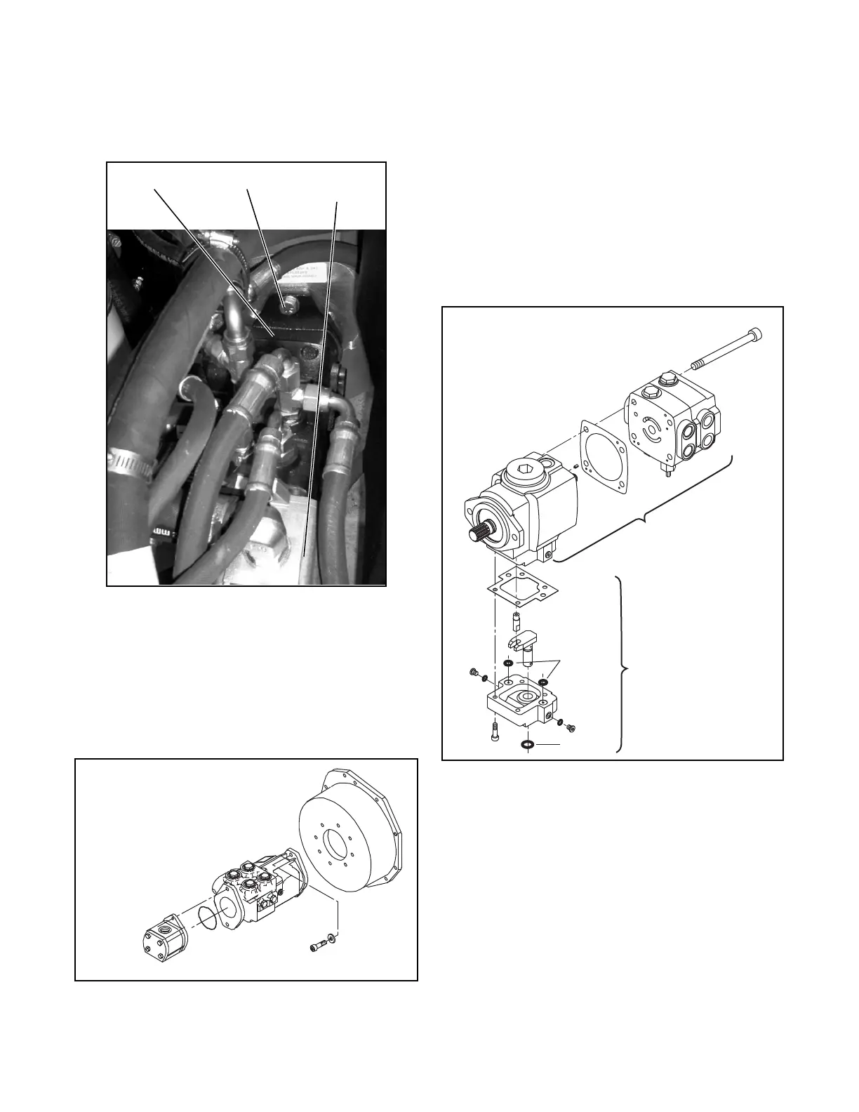
6. While supporting the traction pump and implement
pump, remove the two hex-head mounting bolts
and washers (Figure 8D-4).
Figure 8D-4. Traction Pump Mounting
7. Remove the traction pump and implement pump
from the bell housing.
8. Remove the two hex-head cap screws that secure
the implement pump to the traction pump.
9. Remove the implement pump and o-ring from the
traction pump (Figure 8D-5).
Figure 8D-5. Traction Pump
DISASSEMBLY
Control Group and Valve Plate
1. Place traction pump on a workbench with input
shaft down.
2. Completely loosen, but do not remove socket
head capscrews.
3. Remove the valve plate/charge pump and rear
valve plate as an assembly (Figure 8D-6).
Figure 8D-6. Control Group and Valve Plate
Disassembly
Traction
Pump
Mounting
Bolts
Implement
Pump
Bell
Housing
Traction
Pump
Implement
Pump
Mounting Bolts
O-Ring
Socket Head
Cap Screws
Valve Plate/Charge
Pump and Rear
Plate Assembly
Gasket
Main Case
and Input
Shaft
Gasket
Control Pin
O-Ring
Control
Housing
O-Ring
Valve Plate
Disassembly
Control Group
Disassembly
 Loading...


