CONTROLS
2C-8
5. Pull the linkage away from the pedal until the
brake shoes just contact the brake drum
(Figure 2C-8). Thread the end yoke onto the link-
age rod until there is a 0.75 - 1.0 in of free pedal
movement. Tighten the end yoke jam nut to
secure the rod end.
6. Install the pin through the end of the yoke and
install the cotter pin.
7. Connect the brake return spring (Figure 2C-7).
Repeat for the remaining parking brake assembly.
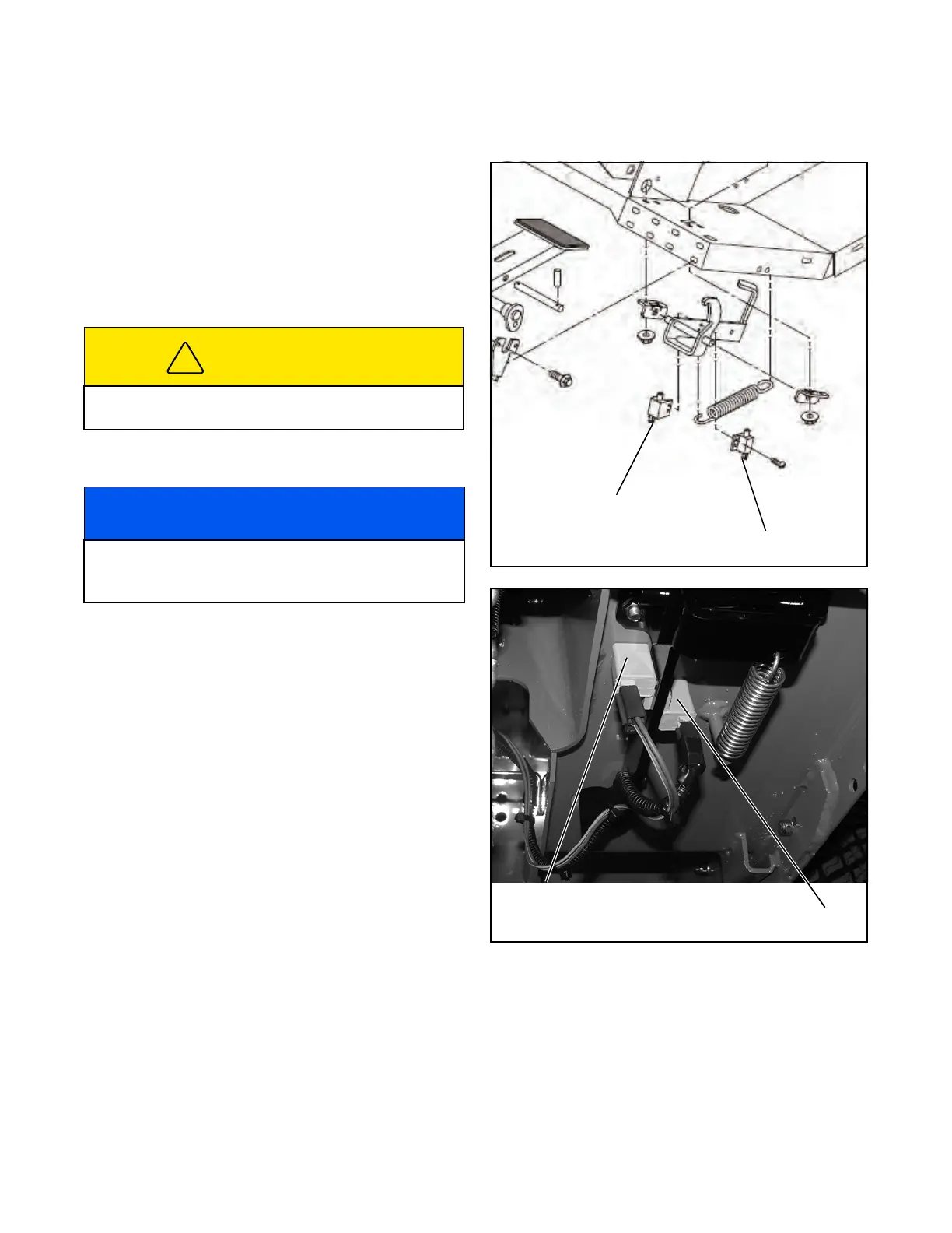
BRAKE INTERLOCK SWITCHES
With the engine off, key switch off, and both brake
switches disconnected, engage the parking brake and
adjust the brake switches as required to close the
switch contacts when the pedal is pressed and locked
and to open the switch contacts when the brake pedal
is unlocked and released (Figure 2C-8).
Figure 2C-8. Parking Brake Switches
Figure 2C-9. Parking Brake Switches
CAUTION
Do not overtighten the brake rods or the brakes may
drag and lock up at transport speeds.
NOTICE
Use a multimeter and perform a continuity test on
both brake switches to determine when the switch
contacts open and close.
Parking Brake Switch
Parking Brake Interlock Switch
Parking Brake Switch
Parking Brake Interlock Switch
 Loading...


