STEERING
6C-8
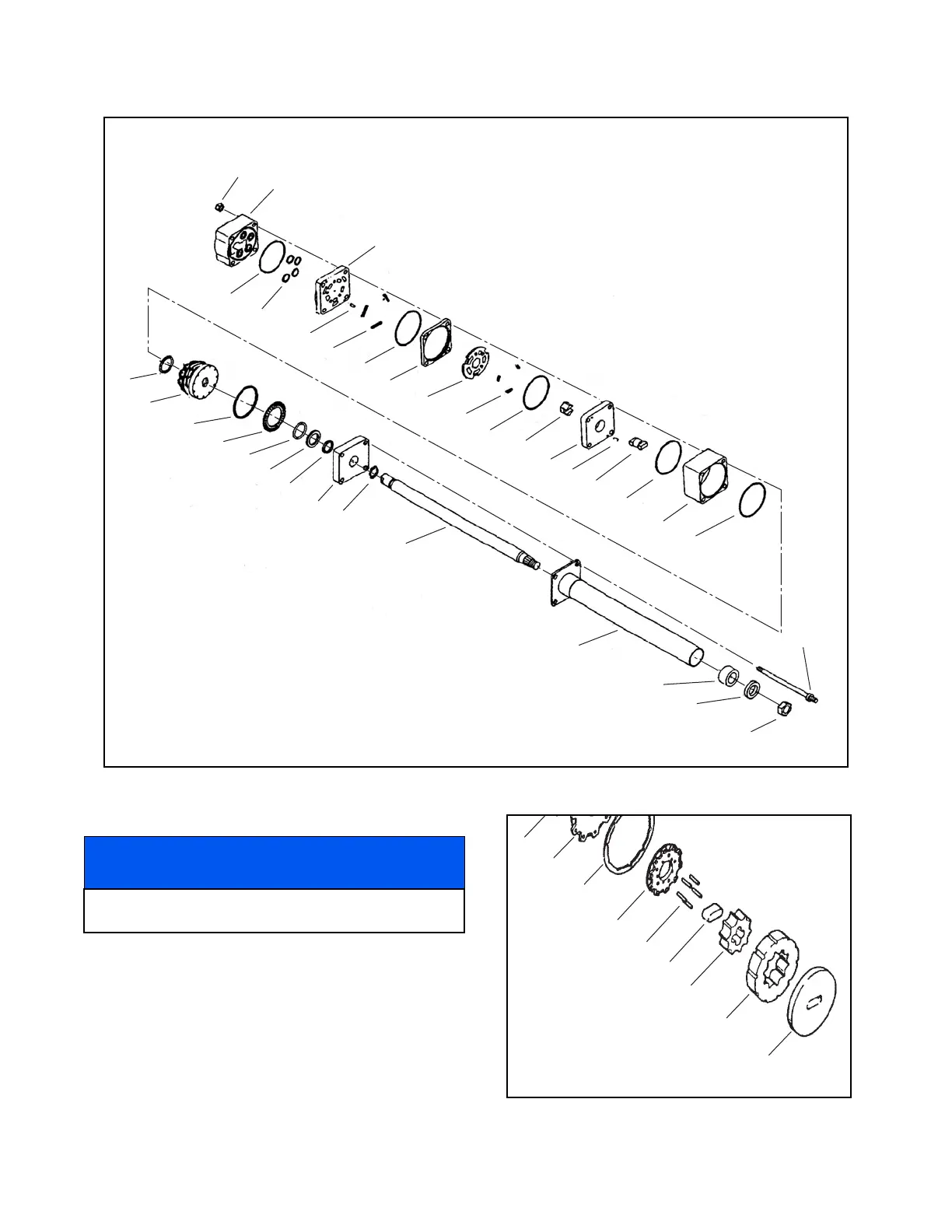
Figure 6C-3. Steering Valve Exploded View
9. Remove the socket head capscrews (1), commu-
tator cover (2), commutator ring (3), and commu-
tator (4).
10.Remove the five alignment pins (5).
11.Remove the drive link spacer (6), rotor (7), and
stator (8) from the drive plate (9).
Figure 6C-4. Metering Package Disassembly
1
2
3
4
5
6
7
3
8
9
10
3
11
13
14
3
15
3
16
17
18
19
20
21
22
23
24
26
27
28
29
25
Steering
Wheel Nut
1. Nut
2. Port Cover
3. Seal Ring
4. O-Ring
5. Needle Roller
6. Port Manifold
7. Spring
8. Valve Ring (Matched Set)
9. Valve Plate (Matched Set)
10. Spring
11. Hex Drive Assembly
12. Alignment Pin
13. Isolation Manifold
14. Drive Link
15. Metering Ring
16. Commutator Seal
17. Metering Package
18. Spacer
19. Thrust Bearing
20. Face Seal
21. Backup Ring
22. Seal Spacer
23. Upper Cover Plate
24. Retaining Ring
25. Special Bolt
26. Steering Shaft
27. Steering Tube
28. Bushing
29. Seal
12
NOTICE
The following steps reference Figure 6C-4 unless
otherwise noted.
 Loading...


