Groundsmaster 4100--D/4110--D Hydraulic SystemPage 4 -- 73
Adjustment of the traction linkage should be checked
whenevertractiondrivec omponents arereplacedorre-
moved.
Assembly Adjustments
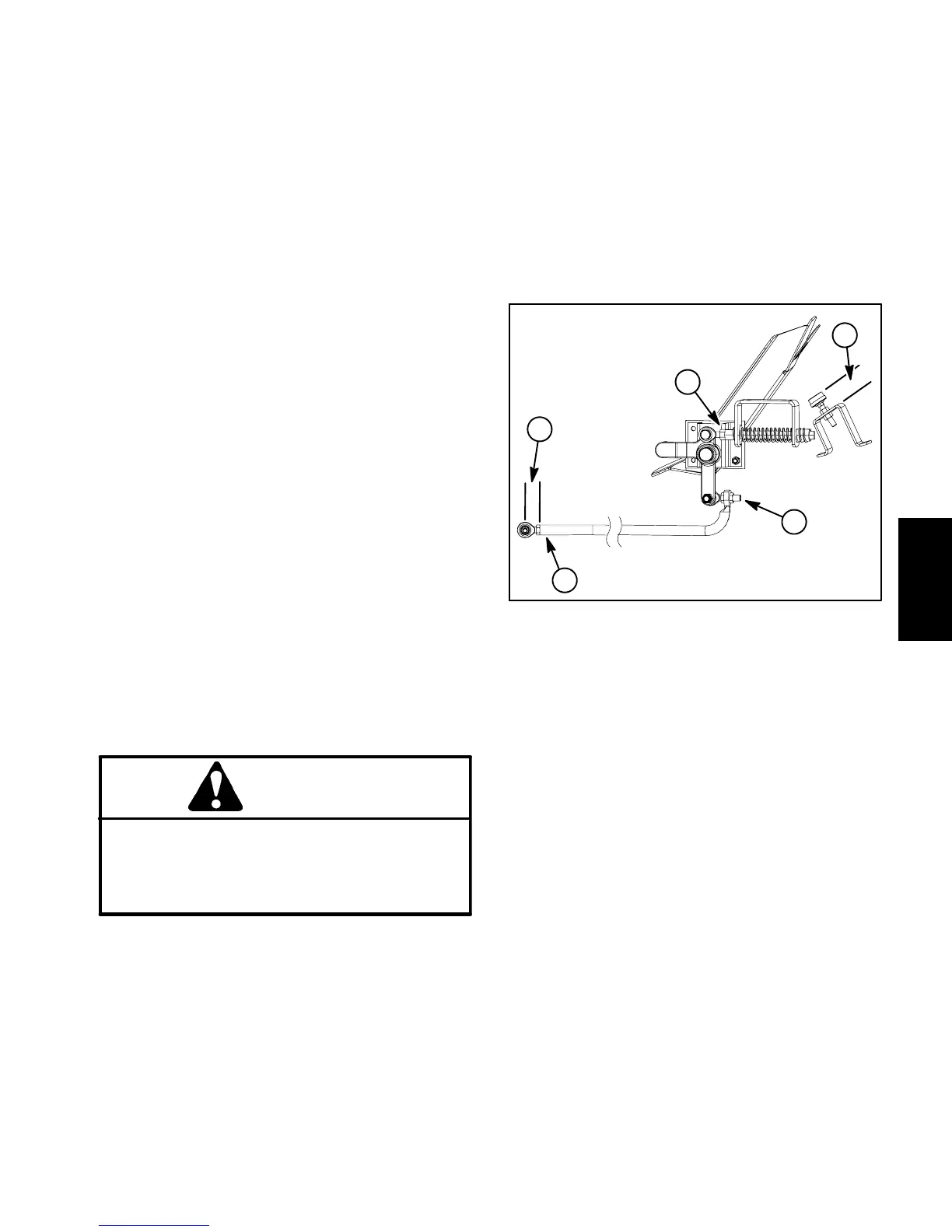
1. Tractionpedalstopshouldbe1.500”(38mm)above
platformbracket (item 1 inFig.53). Ifnecessary,loosen
jam nuts and adjust stop location. Make sure that both
jam nuts are tightened to secure adjustment.
2. On traction pump end oftractionrod, rod endshould
be installed so that distance from end of traction rod to
center of rod end is 1.140” (29 mm) (item 3 in Fig. 53).
Tighten jam nut to secure rod end to traction rod.
3. On traction lever end of traction rod (item 4 in Fig.
53), jam nuts should position traction rod so traction
pedal remains in the neutraldetent position and is atan
approximate 56
o
angle. Use a magnetic protractor to
check pedal angle.
4. With ignition switch in the ON position (engine not
running),useDiagnostic Displaytomakesurethatneu-
tral switch is closed when traction pedal is released to
theneutraldetentposition(seeDiagnosticDisplayinthe
Troubleshooting section of Chapter 5 -- Electrical Sys-
tem).
5. The traction pedal should contact the pedal stop
when fully depressed. At this point, the piston pump
should be at full stroke.
6. To check and adjust neutral position:
A. Make sure hydraulic oil is at normal operating
temperaturebyoperatingthemachineunderloadfor
approximately ten (10) minutes.
CAUTION
All wheels w ill be off the ground and rotating
when checking neutral position. Make sure ma-
chine is supported so it will not move and acci-
dentally fall to prevent injuring anyone near the
machine.
B. Raise and support machine so all wheels are off
the ground (see Jacking Instructions in Chapter 1 --
Safety).
C. When traction pedal is released from either for-
ward or reverse, pedal should return to the neutral
position and wheels should stop rotating.
D. Ifnecessary,adjustspringshaft(item5inFig.53)
until neutral operation is correct.
E. Lower machine to ground.
7. After adjustmentshavebeenmadeand allfasteners
aretightened, makesurethattraction roddoes not con-
tact anything through both forward and reverse direc-
tions.
1. Pedal stop height
2. Traction pump end
3. Rod end dimension
4. Traction lever end
5. Neutral adjustment
Figure 53
1
2
3
4
5
Hydraulic
System
 Loading...


