Groundsmaster 4100--D/4110--D Page 6 -- 5 Axles, Planetaries and Brakes
Removal (Fig. 1)
1. Park machine on a level surface,lowercuttingdeck,
stop engine and remove key from the ignition switch.
2. Drainoilfromplanetarywheeldrive/brakeassembly.
CAUTION
When removing front wheel, use correct jacks
andsupports.Make suremachine isparkedona
solid, level surface such as a concrete floor.
Prior to raising machine, remove any attach-
ments that may interfere with the safe and prop-
erraisingofthemachine.Alwayschockorblock
wheels. Use jack stands to support the raised
machine. If the machine is not properly sup-
portedbyjackstands,the machinemaymoveor
fall, which may result in personal injury.
3. Chockr earwheelsandjackupfrontofmachine(see
JackingInstructionsinChapter1--Safety).Supportma-
chine with jack stands.
4. Tilt the cutting deck upright to allow front wheel re-
moval (see Operator’s Manual).
5. Remove front wheel assembly.
6. Remove hydraulic wheel motor (see Front Wheel
Motors in the Service and Repairs section of Chapter 4
-- Hydraulic System).
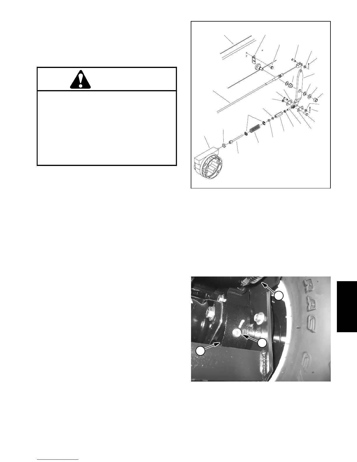
7. Disconnect brake link assembly from brake lever,
frame bracket and pull rod on brake assembly (Fig. 2).
8. Support brake assembly to prevent it from falling.
9. Remove flange head cap screws (item 9) securing
brake assembly to frame.
10.Remove brake assembly from machine. Be careful
tonotdrop splinedbrake shaft(item3)asbrakeassem-
bly is removed.
11.Remove splined brake shaft from brake assembly.
12.Remove and discard gasket (item 11). Make sure
that all gasket material is r emoved from both brake and
planetary assemblies.
13.Completebrakeinspectionandrepair(seeBrakeIn-
spection and Repair in this section).
1. Brake lever
2. Thrust washer (2 used)
3. Flat washer
4. Lock nut
5. Bushing
6. Clevis pin
7. Lock nut
8. Cap screw
9. Brake link
10. Rod end (LH thread)
11. Jam nut (LH thread)
12. Hex link
13. Flanged spacer
14. Compression spring
15. Brake link
16. Brake assembly
17. Jam nut
18. Spring plate
19. Jam nut
20. Brake cable
21. Flat washer
22. Cotter pin
23. Screw (2 used)
24. Cable bracket
25. Frame rail
Figure 2
2
3
6
8
9
10
11
13
1
5
7
12
14
15
16
17
18
19
20
4
21
22
25
24
23
9
22
21
6
1. Brake housing
2. Check plug
3. Brake link assembly
Figure 3
3
1
2
Axles, Planetaries
and Brakes
 Loading...


