Groundsmaster 4100--D/4110--DPage 6 -- 6Axles, Planetaries and Brakes
Installation (Fig. 1)
1. Install splinedbrake shaft(item3)into brakeassem-
bly. NOTE: The stepped end of the splined brake shaft
must be aligned toward the hydraulic wheel motor (Fig.
4).
2. Applygaskets ealanttosealingsurfacesofnewgas-
ket (item 11). Apply gasket to brake assembly.
3. Install brake assembly to machine, aligning splined
brake shaft with input shaft on planetary wheel drive.
4. Secure brake assembly to planetary assembly with
four (4) flange head screws (item 9). Tighten screws in
a crossing pattern to a torque from 75 to 85 ft--lb (101
to 115 N--m).
5. Secure brake link assembly to pull rod on brake as-
sembly, frame bracket and brake lever (Fig. 2). Brake
linkendshouldbecompletelythreadedontopullrodbe-
fore tightening jam nut.
6. Install new O--r ing on hydraulic wheel motor. Install
wheel motor and torque cap screws from 75 to 85 ft--lb
(101 to 115 N--m).
WARNING
Failure to maintain proper wheel lug nut torque
could result in failure or loss of wheel and may
result in personal injury.
7. Install front wheel assembly.
8. Lower machine to ground. Torque wheel lug nuts
from 85 to 100 ft--lb (115 to 135 N--m).
9. Pivot the cutting deck down (see Operator’s Manu-
al).
10.Make sure drain plug is installed in bottom of brake
assembly. Fill planetary wheel drive/brake assembly
withSAE85W--140gearlube.Capacityisapproximate-
ly 16 fl. oz. (0.47 liters) per wheel.
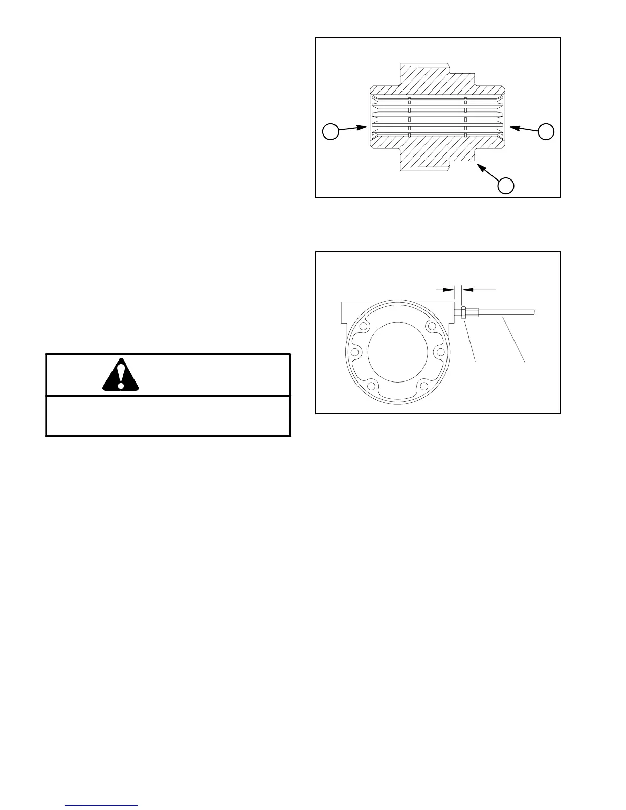
11.Check and adjust brake cables for proper brake op-
eration. If necessary, adjust hex link (item 12 in Fig. 2)
sothatpull rodjam nutispositionedfrom0.470to0.530
in. (12.0 to 13.4 mm) from brake casting surface when
brakes are disengaged (Fig. 5).
1. Splined brake shaft step
2. Hydraulic motor end
3. Planetary assembly end
Figure 4
1
2
3
1. Pull rod jam nut 2. Brake link
Figure 5
1
2
0.470 to 0.530 in.
(12.0 to 13.4 mm)
 Loading...


