Groundsmaster 4100--D/4110--D Cutting DeckPage 8 -- 7
Removal (Fig. 1)
1. Position machine on a clean, level s urface. Lower
cuttingdeck,stopengine,engageparkingbrakeandre-
move key from the ignition switch.
NOTE: Removal of clevis pins from deck and height--
of--cut chains is easier if deck is lifted slightly.
2. Remove hairpins and clevis pins that secure the
height--of--cutchains tothe rearofthecuttingdeck (Fig.
2).
3. Remove hydraulic motors from cutting deck (see
CuttingDeckMotorRemovalintheServiceandRepairs
Section of Chapter 4 -- Hydraulic System). Positionmo-
tors away from cutting deck.
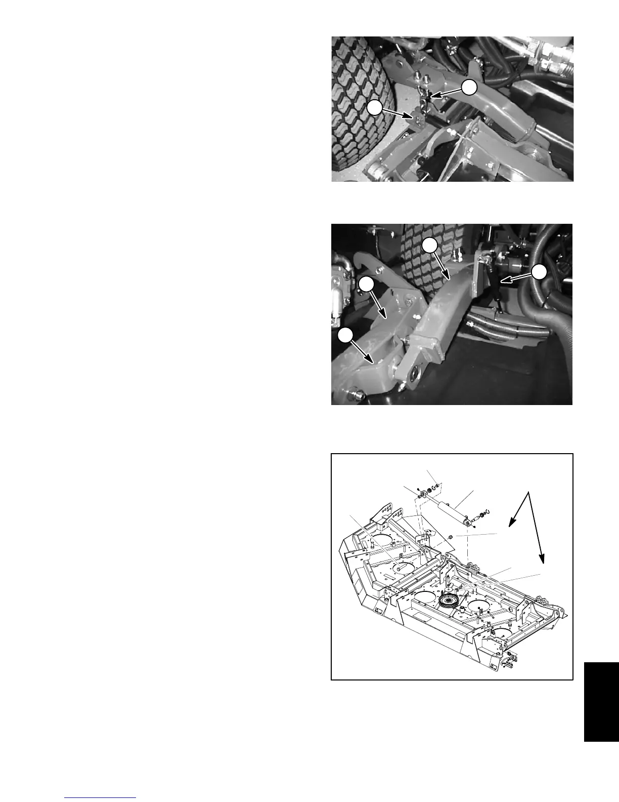
4. Remove hairpins and clevis pins that secure damp-
erstoliftarms(Fig.3).Rotatedampersandplaceonc ut-
ting deck.
5. Remove hydraulic hoses from wing deck lift cylin-
ders (Fig. 4):
A. Remove deck covers to allow access to wing
deck lift cylinders.
B. Thoroughly clean exterior of wing deck lift cylin-
ders and fittings. For assembly purposes, label hy-
draulichoses toshowtheir correctpositiononthelift
cylinders.
C. Disconnect hydraulic hoses from wing deck lift
cylinders.Caphosesandfittingstopreventcontami-
nation.
6. Disconnectcuttingdeckwireharnessfrommainma-
chine harness (Fig. 5).
7. Remove cap screws, flat washers and flange nuts
that secure support hubs to cutting deck castor arms
(Fig. 3).
8. Slide the cutting deck away from the traction unit.
Installation (Fig. 1)
1. Positionmachineonac lean,levelsurface.Lowerlift
arms, stop engine, engage parking brake and remove
key from the ignition switch.
2. Position the cutting deck to the lift arms.
3. Alignsupporthubtocuttingdeckcastorarmsandse-
curewith capscrews, flat washers and flange nuts (Fig.
3). Torque flange nuts from 75 to 85 ft--lb (102 to 115
N--m).
1. Hairpin and clevis pin 2. Height--of--cut chain
Figure 2
1
2
1. Lift arm
2. Castor arm
3. Support hub
4. Damper
Figure 3
1
2
4
3
1. Wing deck lift cylinder
2. Flat washer
3. Lock nut
4. Lock nut
5. Cap screw
6. Spacer
Figure 4
4
3
5
6
1
2
160 to 180 ft--lb
(217 to 244 N--m)
6
Cutting
Deck
 Loading...


