Chapter 6 Network Wiring
150 BMTW-SVN01F-EN
Trane recommends that the first BCU device start at address 01 and that
all additional BCUs be incremented sequentially. For the location of the
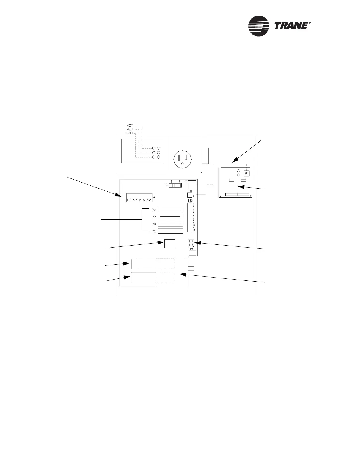
BCU logic board DIP switch, see Figure 69.
In the PC, the device ID is set up as part of site configuration. If ARCNET
is used, always set the ARCNET address to match the device ID (see
Table 29 on page 151).
Figure 69. BCU (BMTW) Device ID: DIP Switch Location
4 AMP MAX
SET UP TOOL
ONLY
ON OFF
ON
S2
BCU I/O module
cable
Optional BCU I/O
module
Seven-segment
LED display
Option card
slots
High capacity
card slot
Standard capacity
card slot
UCM communication
card slots
Operator
display socket
BCU DIP Switch (S2)
Location

 Loading...


