DNR-X-1G Series RACKtangle and HalfRACK Systems
Chapter 2 15
The DNR-12-1G Series RACKtangle System
October 2018 www.ueidaq.com
508.921.4600
© Copyright 2018
United Electronic Industries, Inc.
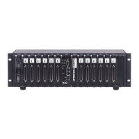
Figure 2-11. DC Power Module LEDs
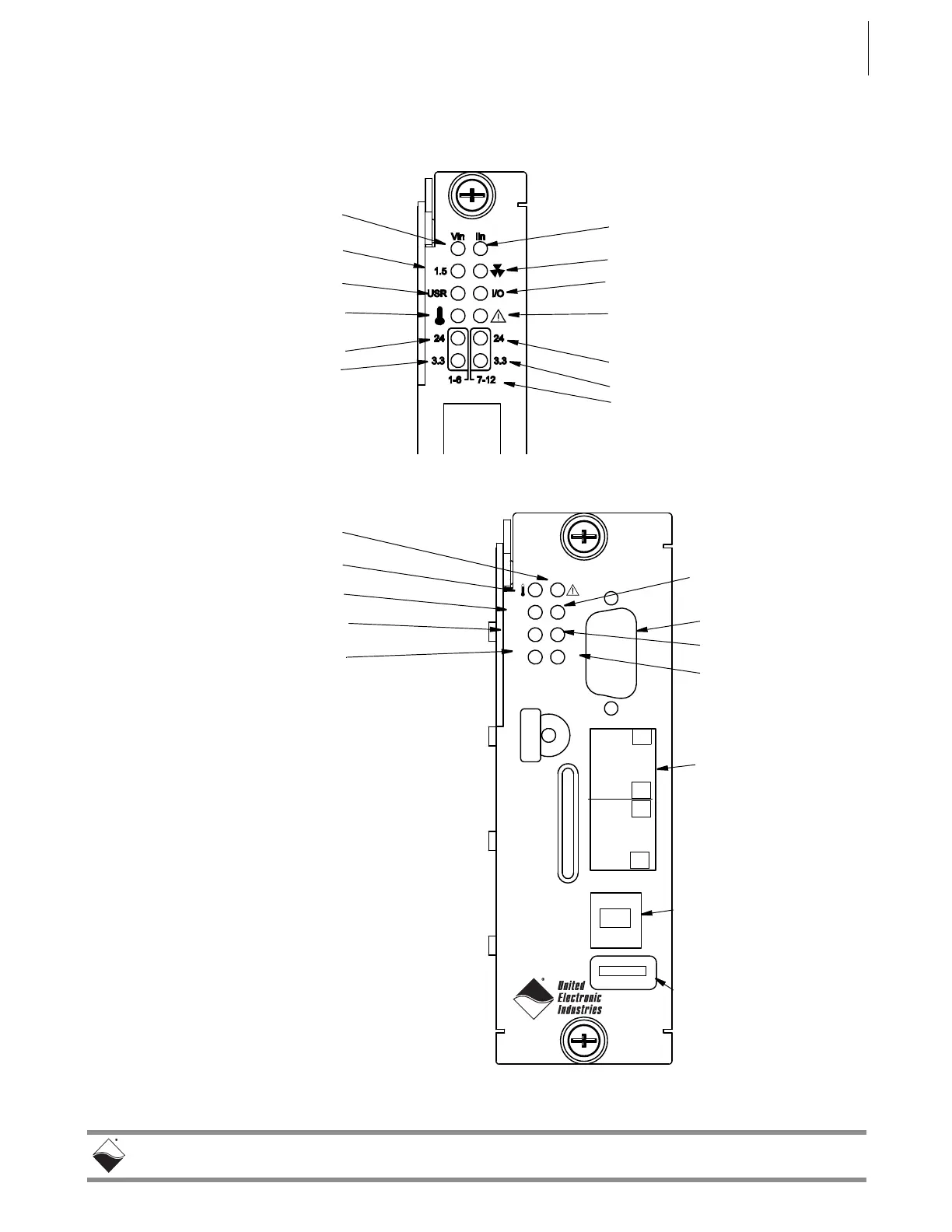
Figure 2-12. DNR-CPU-1000/-XX Module LEDs
Input Voltage OK/Error
1.5VDC OK/Error
User Controlled/Off (default)
LED ON/Off means:
Input Current OK/High
Fans On/Off
I/O Circuit OK (flashes 1/sec))
LED ON/OFF means:
24VDC OK/Error -- Modules 7-12
3.3VDC OK/Error -- Modules 7-12
24VDC OK/Error -- Modules 1-6
3.3VDC OK/Error -- Modules 1-6
When flashing, module needs
Temp High/OK
Module Groups
attention
SD Card
USB B
USB A
NIC 1
NIC 2
Sync/Reset
RS-232
3.3
24
COM
USRR/W
PG
When Flashing,
Read/Write Activity
Serial Comm. Activity
Power Good
Module Needs Attention
Note: On a UEIPAC CPU/NIC module,
the LEDs are user-programmable.
Temp High/OK
USB 2.0 Controller Port
Type A Connector
USB 2.0 Slave Port
Type B Connector
(reserved for future use)
(reserved for future use)
Ethernet Ports
NIC1 (Main),
Serial Port
User Controlled/Off
3.3VDC OK/Error
24VDC OK/Error
NIC2 (Secondary)
 Loading...