DNR-X-1G Series RACKtangle and HalfRACK Systems
Chapter 4 48
Installation and Configuration
October 2018 www.ueidaq.com
508.921.4600
© Copyright 2018
United Electronic Industries, Inc.
STEP 5: Connect the DNR-X-1G to your PC’s second NIC using a CAT5 cable. The
green LEDs on the DNR-X-1G NIC2 should light up.
STEP 6: Ping the DNR-X-1G system from the command prompt on the host PC to make
sure that it is alive (the following shows a successful response):
C:\> ping –n 1 192.168.100.2
Pinging 192.168.100.2 with 32 bytes of data:
Reply from 192.168.100.2: bytes=32 time<1ms TTL=128
Ping statistics for 192.168.100.2:
Packets: Sent = 1, Received = 1, Lost = 0 (0% loss),
NOTE: A “Request Timed Out” message indicates an error.
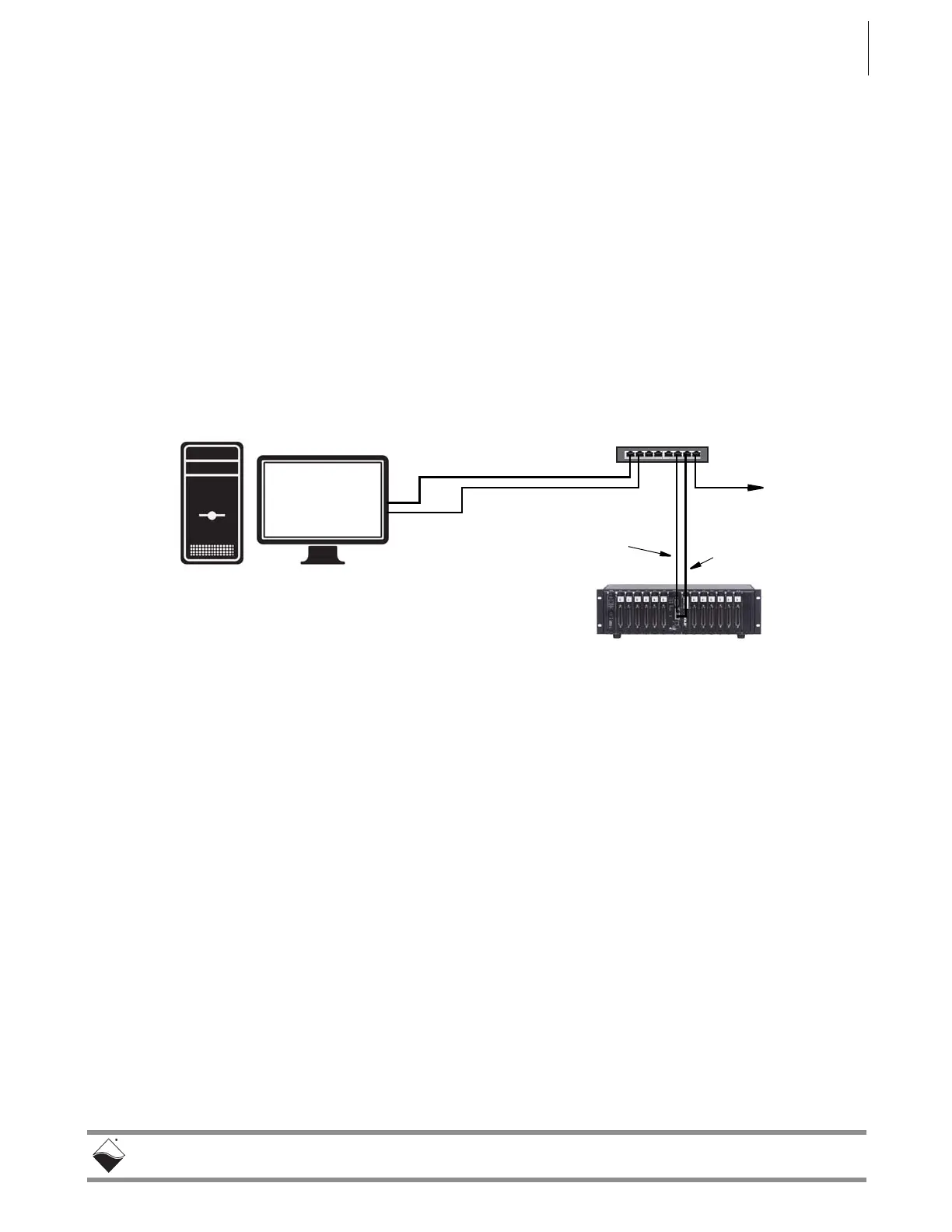
STEP 7: The system should now be configured as shown in Figure 4-7.
Figure 4-7. Typical Configuration for a Single DNR-X-1G with a LAN
Switch
STEP 8: You may now use PowerDNA Explorer to view system network settings and
communicate with your system.
(Refer to Chapter 5 for more information about PowerDNA Explorer, if needed.)
NIC1 - 192.168.1.10
NIC2 - 192.168.100.3
(Diagnostics)
Primary
Port
Diagnostic
Port
 Loading...